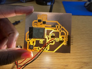
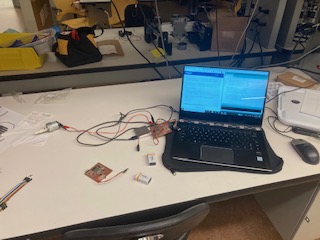
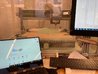
Hello! My name is Timi Omotunde. I am current Senior (undergrad) majoring in Electrical Engineering and Computer Science and minoring in Applied International Studies. My main reason for taking this class is to get more fluent in STEM teaching.
Getting Started
One of the big things that I wanted to work on this week is design. Throughout my MIT time, I have been focusing on the math and science of how things work, but not the math and science of how things look, which can be equally important. Look at the Stud! For this project, I aimed for utility and aesthetic.
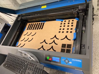
With that in mind, I created a cardboard set allowing you to make buildings, shapes and more. The things that I will demo will be a pair of glasses for a giant, an Ipad holder and a small table. I also made - and included photos - of other quirky, cool shapes I was able to make out of my pieces.
One thing worth mentioning is that I only made three pieces in Fusion to make all the shapes I did [INSERT PHOTOS]. You'll notice that there is a semi circle missing from the sides of the long pieces, that is purely aesthetic design for appeal. Additionally, I did not chamfer or fillet my pieces in Fusion. I did this purposely as I wanted to see how precise/snug it would have to be to fit well before I moved on to improved designs. The thinking here was that I may be overengineering pieces in the future, if there is not problem with simpler shapes. In engineering I have learned, do not complicate things, if they can be solved simply.
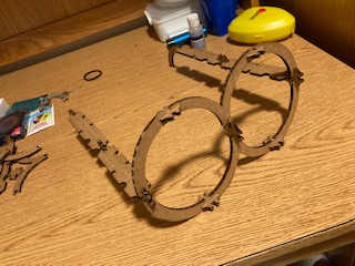
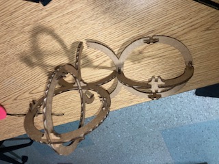
In this first photo, I wanted to use as many pieces as possible from the pieces that I cut out. Thus, I made a pair of glasses. The inspiration came from my wearing glasses and a friend who was able to visualize it just from the amount and type of pieces I had.
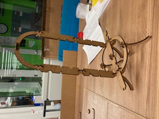
The my second photo, I may an Ipad holder. It may not be truly functional because the cardboard isn't too strong, but hey I may be able to use it for my phone. Additionally, if I were to re-cut this with acrylic it would be more than strong enough to hold an Ipad.
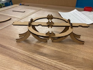
In my last demo, I made a little table. This type of design was what I envisioned when I started this project, mock-up of cool/old looking designs.
<
Moving on to vinyl cutting, I really loved the idea of vinyl cutting. It is truly novel. However, I foreshadow that in a normal semester, I would use it a lot more - especially for my final project. However, in our shortened schedule, I do not believe I will have enough time to prototype and then move onto the vinyl cutting. In truth, I loved vinyl cutting and would love to do a final project revolving around the concept. Time willing, I will cut copper on the vinyl cutter.
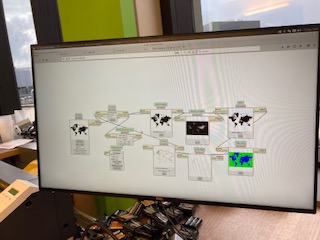
In beginning to vinyl cut in the EDS, you need to reboot the computer and run in on its linux operating system so that you can access the appropriate MODS. The EDS computer has two operating systems. For this vinyl cut, I chose to cut out a sticker of the world. I love traveling and hope to work internationally.
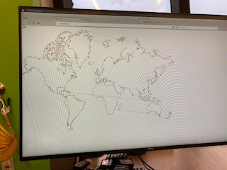
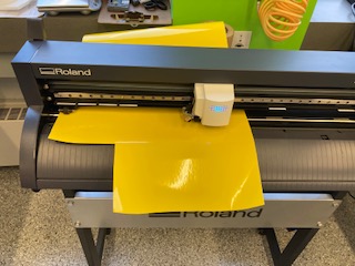
In the above photo, I am showing you the tool path for the vinyl cutter. The machine is quite interesting since it can only cut in one direction, but is able to get some precise cuts. However, in my case, the vinyl cutter was not so precise near the edges. I am not quite sure what happened. My best guess is that mods made a mistake and did not transfer the code to the vinyl cutter correctly. Thus, you'll see parts of Russia and New Zealand missing from my world map even though they are present in the toolpath - the cutter did not even attempt to cut these areas. I re-cut the image three times to make sure it was a human error.
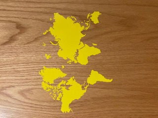
In finally transfering the cut to a surface, I originally tried cardboard, in keeping with the theme for the week, but I was not successful as cardboard looked terrible for photos. So, I transfered it to the door on my closet. It had a nice woooden finsih, and I reasoned it would be picture perfect.
View Week 1's group assignment here
On the move
For this week, I decided print a mockup of my final prjoect. Additionally, I added in various features to test the quality of the 3D printer. I was happy to see the resolution came out well, but I was disappointed to see the fillets and chamfers did not come out quite as I hoped. Overall, I am quite happy with the printers as I have used really bad printers before. For the 3D scanning portion of this week, I first tried scanning my Airpod Pro case, however, the item was to small for the scanner and it picked up part of the background. Second, I tried scanning an acetone bottle that happened to be near the lab bench, but the scanner kept losing track of the item even though I was not moving it. Lastly, I tried a wooden doorstop wedge. That item worked surprisingly well in comparison to my two previous objects. However, I had to delete the backgound in post editing. In short, I do not think I will be using the 3D scanner anytime soon.
Getting into the details for the week, I want to cover everthing as it happened. Worth noting, I have a decent amount of 3D printing experience, so nothing eventful truly happened outside of the 3D Scanning portion. [INSERT MORE PHOTOS]
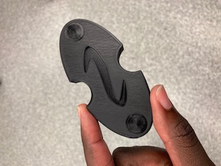
As stated previously, I wanted to do a not to scale mock up of what my final project may look like. The idea at the moment is to make a two-way radio (a walkie-talkie on the AM band) I have actually made a beefy circuit of a walkie talkie on the legal AM band that uses illegal transmission power to broadcast up to a few miles away. I made this for 6.101, an analog laboratory, for this class, I demo'd a walkie talkie abiding by legal power transmission standards. In fitting with that classes theme, everything was made up of basic electrical parts, even the oscillator! For basic electrical parts think MOSFETs, resistors, capacitors, and inductors. It was a super cool experience that I hope to transfer over to this class. However, since we need to use a microcontroller in the final project, I may do something else as a microcontroller would make a walkie talke obsolete as there would already be more and better communication protocols on the chip. However, I digress
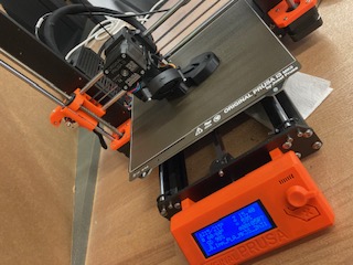
Getting into what I did, the shape is one part what the casing of my final project may look like and another part me testing the capabilities of the 3D printers in the EDS. I chose to print this on the least capable printer in the workspace, the prusa (Maybe this is the name?). I believe this printer was home made like the clank. For what it was the printer did a pretty good job, I was pleased with the overall resolution. However, the resolution on the curves was not as nice as I was expecting. I know if I went with a better printer in the lab this would be less of a problem. I wasn't able to use the nicest printer in the lab as the belts were broken, and the operating company wanted to replace the printer for the cool prince of $1,000+ rather than repairing it for $40. Gotta love capitalism. I know for my final project, I will definetly be using the higher end printers - even if they take a little longer. However, this is far from serious and a good way to get acclimated to the abilities of the printers I may be using in the lab.
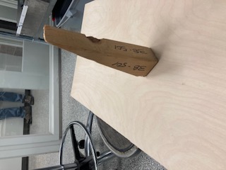
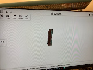
As noted previously, my 3D scanning experience was pretty tough. In the EDS there are two 3D scanners, but only one really works. Meaning there's only one 3D scanner in the EDS. It goes to show quality cannot be matched - meaning that $700, a large sum of money, does not gurantee quality. Funny enough, the company that manufactured these scanners no longer sell this particular item. Getting back on topic, after waiting in line for the 3D scanner, I realized it was in my best interests to not scan something complex as the 3D scanner did not work as well as it could have. In a perfect world I would have tried to scan my head and print a 3D bust. However, I do not live in a perfect world. I knew, after watching multiple people struggle to get anything recognizable, the scanner was fickle. So I tried to scan my Airpod Pro case. Things did not go well and the scanner through a variety of errors like "Moving too fast," "Image lost," etc. I tshould be noted I was not evven moving at some points and it would through these errors. In theory, it should not have as I had not moved the scanner to a new location by a centimeter. After a while, I tried going for a bigger item as maybe my airpods being as small as they are was complicating things. That was not wrong, but it did not help things as much as it could. After my Airpod Pro case, I tried using an item someone else had already successfully scanned. Agian, I had no luck. The item was an ethanol squrit bottle with a red top with a nozzle bent at a 90 degree angle.The 3D scanner, having a mind of its own said, "I may have worked for someone else 10 minutes ago, but I will not cooperate with you!" Thus, I had to struggle with an even simpler image, a triangular door wedge. It scanned. But, as you can see not well. I had to clean up the image in post processing. To be fair, I am glad that I managed to get something. I would like to use a higher end 3D scanner like they have in the media lab to see what they can actually do.
View Week 2's group assignment here
Towers of Petronas
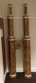
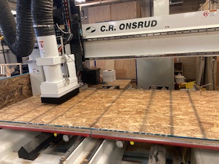
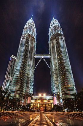
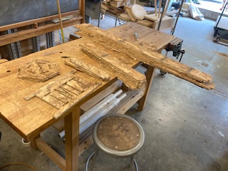
For this week, I took a little more time than usual in coming up with what I planned to create. It is not often you get the chance to build with a 4'x8' piece of wood - not matter how splintery. I knew from the start that I didn't want to build a table - it seemed to easy. Then I realized it would be cool if it were inspired from my travels. Immediately, I thought of recreating the Eiffel tower, but I realized that's a super cliche. Then I thought of the Louvre, but thats also not complicated since its a glorified pyrimad - 4 triangles. Then finally, I realized the Petronas towers in Kuala Lumpur, Malaysia would be an interesting design challenge. Mind you, I am no architect. My main engineering focus lies in electrical things and not support and the physics of moving or immobile parts. Below is a picture of the twin towers.
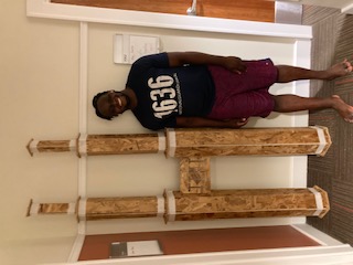
In this week, I created a rough model of the Petronas towers with a sign with my name in place of the skybridge. In the ideation phase, I thought that I could create 2 towers at about 8' high from one piece of OSB. However, at some point during the design, I realized while that may be mathematically possible, it may not be practically possible. So I settled to make one tower and see if there was any scrap wood at the shop I could use - and luckily there was!
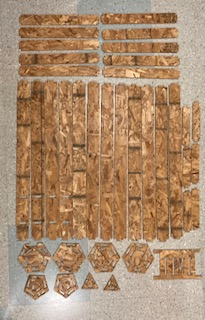
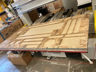
In hindsight, I was motivated and creative in doing the project, but I clearly lacked the know-how and experience to do it well. For instance, I didn't build a base in the initial design as I was not sure if I had the space or if it was necessary. I also thought that I could use six pieces at every tier. All of those assumptions were wrong. A mock building, like an actual building needs a foundation or it will fall. As area space shrinks so does the amount of pieces that can reasonably be included at every stage. Luckily none of these mishaps were fatal. I used the first connector as my base since they were the same size. Furthermore, I realized mid-design that I could use six pieces at the first stage, five at the second stage, and three at the third stage.
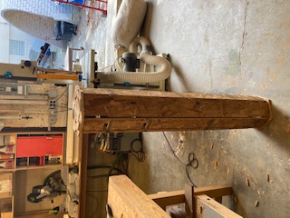
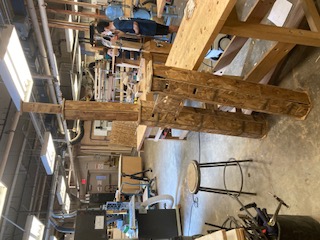
When I put the tower together, it was unstable, I realized I would need something to hold it together, so I took some white tape and taped the ends to increase stability. It worked sruprisingly well, and it could stand tall without support. As a fun fact, I was in an incredible rush when I was in the architecture shop and thought the boards were made too thick as I was fitting them together in the wrong connector. Consequently I took abou 1/16 of an inch off of both sides of all bottom boards on the ends. Even though I thought that was wierd since they fit perfectly in Fusion, I didn't question what I was seeing. This is just a perfect example of slowing down even when you are in a hurry. However, aethestically, it did not ruin the appearance since it was minimal and only at the ends. In terms of aethestics, I think the white tape really makes it pop. Additionally, I substituted in a sign with my name on it for the skybridge. For reference, I am 6' tall and the tower is approximately 7'6".
View Week 3's group assignment here
Vamos a Mexico

This week was pretty exciting. I realized early on that this could be a long week, so I tried to start early due to how the "Make Something Big" week went down to the wire. However, all my efforts were in vain. I wasn't able to mill my block until Tuesday night. Leaving casting until and molding to Wednesday/Thursday.
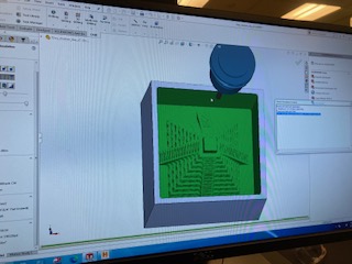
Continuing on the theme of buildings, I decided to mold Chichen Itza in Mexico. I was able to get a file from GrabCad - I know the theme of the class is to build off weeks for which I am sorry, but time was tight in our shortened semester - thinking this would speed up the process. However, when I loaded the file into SolidWorks, the part was oversized by a factor of 100 for a 6"x6"x3" block. However, when we resized the block multiple times in SolidWorks and Fusion, the accompanying plane did not scale down. We are not too sure why this happened as the part should have resized accordingly, but apparently there was somehting in this file that either didn't resize properly or prevented the rest of the piece from resizing properly. Anyway, this wreaked havoc on SolidWork's CAM feature since when it generated the toolpath it was trying to do it for a much larger area size. However, Anthony was able to come up with a solution - a bounding box for the toolpath. With that silhoutte the problem was solved. It may have been faster to make it myself - but lesson learned. The CAM feautre is pretty interesting and something I plan to explore later, personally. Additionally, I have no doubt that I will be milling in some form for my final project, so I will get a round to with SolidWorks CAM.
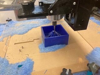
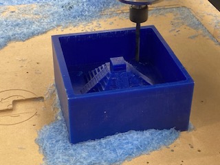
In CAM, I was able to see that the results had pretty good definition for a layered 2D image, we used an adaptive cut. We didn't have enought time to make the milling process 3D, cleaning cut, - which would make it even nicer. However, I was even more surprised to see that 1/4" flat tool was able to capture that definition during the milling process.
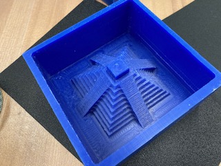
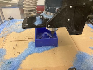
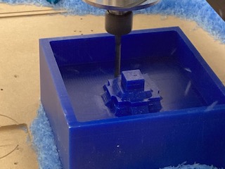
Here are some more photos of the cutting process. It is definitely fun to watch and to vacuum up all the loose wax after!
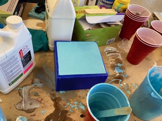
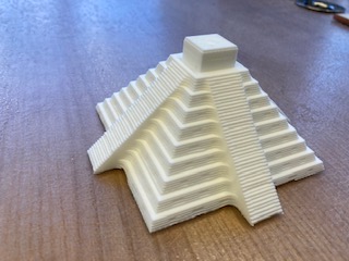
After the milling process, I was able to succesfully mill the wax block, I was able to cast drysone and plastic resolutions. I wanted to cast hydrostone, but there was not enough for a part as big as mine. I wanted the hydrostone cast as it came out in a grey color, something I thought would be perfect for my mock Chichen Itza. However, the plastic and drystone solutions both came out in white. I could have done a colored plastic solution, but I thought that might not look good for what I wanted, a somewhat realistic version of Chichen Itza. True to the perks of molding and casting, I was able to whip out two drystone and three plastic models to distribute out to my pod, who all happened to be of Mexican heritage. As a quick side note for the photos below, the liquid in the cast happens to be the plastic solution and Chichen Itza images happen to be drystone and plastic in that order. As a side, I wanted to cast my model in metal, but Anthony said that it would be very expensive for its size and the resolution might not be as nice as we would want it due to uncontrollable bubbles.

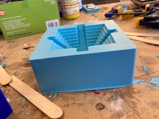
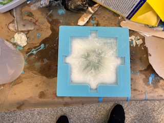
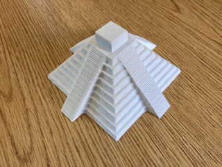
Above is the progression of the model casting, but please enjoy a finished product below.
View Week 4's group assignment here
An Exercise in Time Management
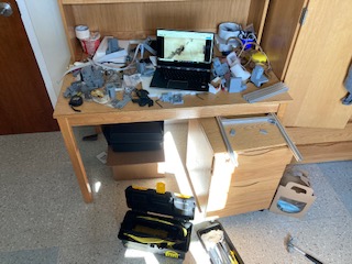
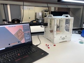
When I first started this week, I was full of excitment for getting my own PCB mill. And when they said we would have to put it together ourselves, I didnt' give it much thought since that would add to the excitment right? Wrong! Over the course of three nights for a probable combined 10ish (maybe even 15 - who's counting?) hours I would assemble this kit right before sleeping, making me go even slower as I am that much more tired. However, I was able to finish and for that I am grateful. However, I am still figuring everything out on the operation side, so who knows.
While putting the clank together was very much a struggle, I really enjoy constructing things, since you get to see the sum of a machine's parts. Furthermore, while I know putting the clank together was fun for me, I think it might be worthwhile to give the kits out at the beginning of the semester, since that would speed up breaking/repair iterations. It would also give people a chance to construct it when they are not as busy. I really enjoyed that there was a fast respone time for clank issues.
In getting into the specfic clank struggles, I felt like things weren't so clearly labeled that I knew if I was doing the correct step at each time point. Really emphasizing what screw or nut is being inserted would go the extra mile in ease of comprehension. At some points, I had to rely on sight and not specific name of what screw Jake was using. Another small gripe I had was that my tension belts were just barely enough to fit in the three spots. This also made it hard to tighten the belts since I couldn't grab anything to extend it.Lastly, some of my 3D printed pieces were somewhat deforemed. Nothing critical to the point of unusuability, but I know others had big issues with this.
Getting into milling, PCB milling is really interesting for me. I have had PCBs made in the past, but I've never actually physically made one. It's somewhat ironic as I am an EECS major with a specialization in the hardware side. Moving on, I actually took a conservative approach and made my PCB in the EDS on the OtherMill as I wasn't quite sure if I had figured everything out on the Clank - and I was right after I left the EDS to run my clank I snapped the 1/32 bit. I also wanted to experiment with hot air soldering which I hadn't done before. Now that I have, I prefer hot air soldering, it's flat out easier in some cases.
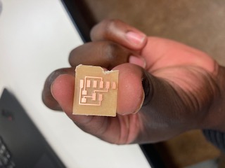
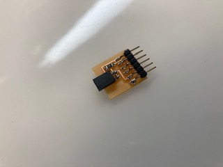
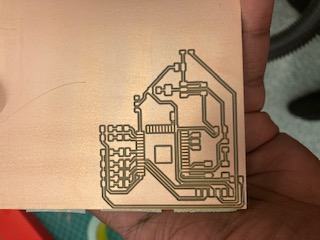
The PCB I made was taken off the website from an example, Brian's I believe, a simple UDPI converter. I would have liked to design my own circuit, more complex, but I did not have time this week with other projects and putting the clank together. I also know that I will be getting plenty of experience in the coming weeks, so I am not too concerned besides closing out the week.
Something interesting that came out of cutting on the othermill is that there are multiple ways that PCB mills, and every mill, can cut according to its toolpath. In the image above you will see that all the material but the copper pads was extracted. In all my future cuts with the clank and the othermill, the only material extracted will be a line alongside the traces and pads. There are pros and cons to each method such as tool time and tool wear and tear and other considerations, however, if I were to pick a favorite, I may prefer the option where all the material is extracted besides traces and pads. This is simply because your soldering job can be sloppier and you don't have to worry about shorts. This would also be helpful when hot air soldering. The solder paste has a way of getting beneath your piece, sometimes causing shorts. However in the other method it would be easier if you are still in an iteration mode as you can cut and reconnect traces as you see fit with minimal magnet wire. However to each there own. However, since time and getting helpled quickly is a major consideration while we are still on campus, I will be using the the line trace method to cut out my boards.
I'm still working out why I broke the bit, but I think that I did not zero the tool correctly. I had it flat on the copper plate, but I think that it was too far down, since it was pushing the plate. I will keep in mind for next time to place it just above and not on the clank base plate. Perhaps it was not fast enough, I will consult with the teaching staff, and hopefully update this section.
This is an update after the fact in December, I think there were multiple things at play. 1. My bed was not flattened 2. My spindle was spinning counter clockwise 3. The MODS speeds weren't optimal 4. I think the zero point was also not optimal and the incorrect MODS feed combined with the above problems exponentiated this. Overall, I think all of these issues would result in a broken bit - some more than others - but combined it's a recipe for disaster. In conclusion, many of these don't need to be addressed anymore, but I think some should be emphasized in the setup or future videos as I know many other people also struggled with these issues.
View Week 5's group assignment here
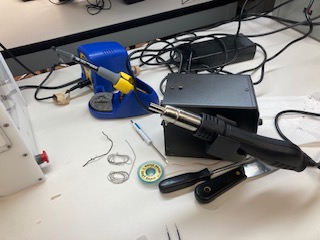
Time to flow
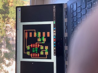
For this week, I recreated the echo Hello World board for the ATtiny412. It was pretty interesting. I knew that I would not be using this board later, so I wanted to get more practice in cutting out the board and hot air soldering. Both of which I learned some pretty important insight and techniques.
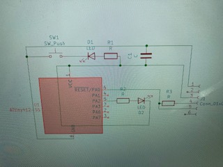
The schematic on the website was pretty complete, however, I had to add some additional components to be able to program the board. In truth, it would have sufficed to have just cut out the board on the website and soldered as necessary since I didn't need to program the board. However, I enjoy going - or attempting - to go the extra mile in this class to take a deep dive. The extra components I added were namely a pinout for the transmitter and receiver pins and a resistor. It should be noted that while the circuit was not complex, getting the traces to fit into the pcb was complex. This really put me off of the AT series, or at least the ATtiny 412. Really, I was put off because it had little computation ability combined with a lack of WiFi or bluetooth ability.
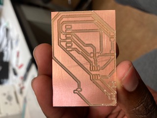
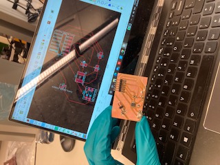
I first realized that you need to make the outline of the board specific to whatever you are cutting out. While I should have automatically realized this, I embarrasingly did not. Moreover, I had prior experience making PCB in KiCAD. However, actually fabbing the board is where things get interesting. While I do prefer the "OtherMill" in the EDS space, I know I need to become more proficient in the clank as I will be able to use that mill after this class ends.
Another technique that I got more insight into was hot air soldering. If you remember last week, my hot air soldering went perfectly. However, this week that was not the case, and I got to learn more about how to do it well. In my first attempt, I put down too much solder paste and had to use a solder wick to get excess solder between parts and off the board. While I was able to get something that worked. I was not able to get something aesthetically pleasing. Yet, I still appreciate the lesson I learned here as I will carry it over into future weeks and my final project, where I know I will be soldering again.
In this section, I just want to provide context on the experience. In truth, I would prefer to use Eagle as Anthony and Premila use Eagle, but I know a little bit of Altium, the better version of KiCAD, and I had already started using KiCAD for a class last spring, 6.101. I figured since my computer didn't have too much space left, the deletion/download process for the softwares would be lengthy enough to disincentive me, and since why fix what's not broke, I kept with KiCAD. Interestingly enough, I tried to edit the design rules in KiCAD, but they didn't stick. The default trace thicknes is ~9.85 thou which is super skinny, so whenever, I want to change that thickness, I have to go in manually for each project and adjust it. Same for the vias. In the future, I want to try making a two sided board. I know it will be easier with the othermill, since I dont need to try to line things up as neatly, but I also want to try with the clank because I will have the clank for perpetuity. Lastly, I learned that solder wick works alright on its own. But, when you combine solderwick and flux, sparks will fly. I am serious, depsite repeated solder experiences, I had to take this class to figure that out. In my defense, solder wick was widely talked about or available in said experiences. This class truly does teach you how to make (almost) anything.
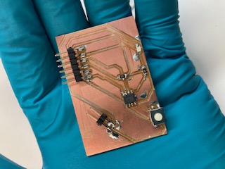
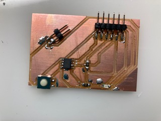
View Week 6's group assignment here
Putting it all together
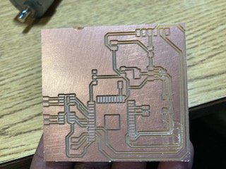
For this week, I realized that this would be the perfect time to get a head start on my Final Project and put together all the skills that we have been accumulating for the past few weeks. For this week I aimed big. I wanted to make the electrical schematic for my RC car in order to test it and verify that all components worked. It would put me ahead of schedule and on track to finish before all undergraduates are kicked off campus after Thanksgiving. However, when you aim large, you run the risk of not finishing on time. And that was me this week. While I was close to the Wednesday deadline I missed it by a few hours. I suceeded in cutting out my board, but not in soldering, programming, and debugging my board. I hope to finish this all by the end of the week.
Here is the datasheet for the ESP32 that I will be referencing from trouble shooting
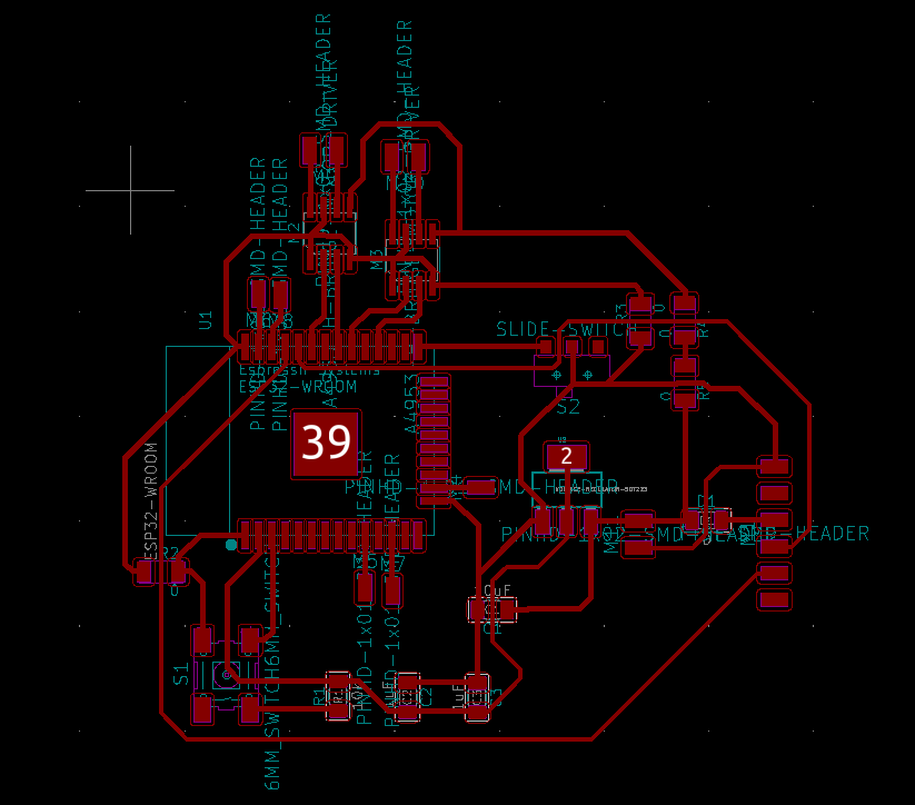
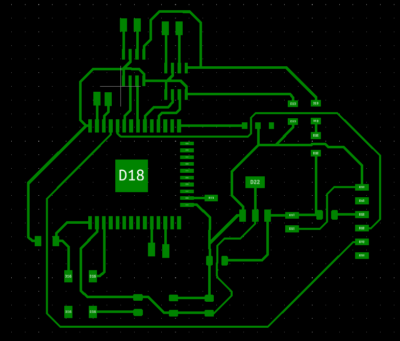
However, let's talk through this week and what happened. The first challenge I encountered was figuring out what parts I needed for my board. To do this I had to read through a lot of data sheets. One for the ESP32, one for the motor, one for the H-bridge, and another for any other unusual part I thought of encountering. After I had to make the schematica and PCB it. From prior knowledge, I know that you shouldn't necesarily make a super clean schematic since it won't translate to the PCB phase and can eat up time if you are pressed for time. However, you should make it readable enough to refer back to it. With these tools, I was able to get it done in a reasonable amount of time. However, I did realize, and somewhat on purpose, that I left out traces since it would be easier to connect them via jumper wires.
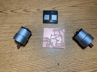
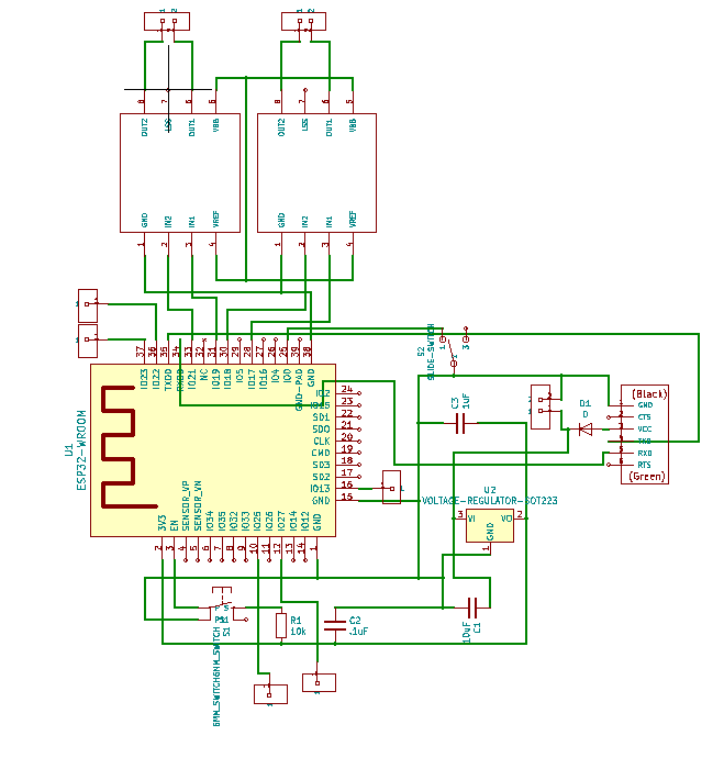
In retrospect, it would have been easier to make this board last week, but I didn't know what I was going to make, so the weeks happened to converge. Additionally, I was pressed for time last week as I had two midterms and was managing an energy conference for 1,000+ people.
Now that I finished, I can report that I was not a few hours shy of the deadline, but days short. Debugging was painful, but incredibley necessary. There happened to be quite a few bumps in the road. Namely, in redesigning the schematic multiple times, I had left out a trace, jumping wires is not as easy as it seems, and hot air soldering can be difficult. At the time I resaosned that since I already new I was going to recut the board because I was putting in an absolute shift on the board (the board was pretty beat up from soldering parts and then desoldering the part) so jumping wires would be necessary. I also rationalized this since I was having some difficulty in getting the wires to stay in place while I was soldering. Additionally, I had trouble soldering with hot air. I will also repeat this for the next week's section since I blurred them together. However, when hot air soldering, the solder paste was getting up under the board causing shorts. Ironically, with the first ESP32 board I didn't have any trouble, but with each following board (until I soldering with an iron) I did have trouble. Life's funny that way. It took me two addtional boards until I realized it was how I was soldering that was messing me up. I was trying to use hot air to expedite my time and not worry about breathing the fumes, but it only cost me time. In hindsight, soldeirng with an iron took less time that the hot air as the setup for hot air soldering can be quite expensive. In truth, all that wasted time cost me 4 valuable lab days before I was able to get a perfectly working circuit. However, I am not truly upset since it was a valuable learning experience. Stick with what you know in a time crunch even if a new method may or may not save you time.
Lastly, I did have some errors with programming my board. It boiled down to attention to detail. For instance, when you program or run the ESP32, you need to pay attention to switch direction is. In one direction, the ESP will execute the program, in another direction the ESP will download code. This got me initially as the Arduino console shot out an error reading "packet content not recived," when the switch was in run mode and not program mode when you want to upload new code. Addtionally, pay attention to your pins. It's been a little while since I used Arduino code, so I accidentally forgot to set the pinouts to INPUTS/OUTPUTS and that got me for a little bit. Overall, this week was a success...eventually :)
View my code to turn on a motor here
View Week 7's group assignment here
Not Touch Sensing!
For this week, I decided to use this week in order to advance on my final project. I knew that I needed an output method to control the motors for my RC car. Funny enough, I actually did this week after week 9 (output devices) as in week 7 I had started to build the board for my motors. Thus, I learned everything necessary to make this week flow as smoothly as possible in comparison to the other board.
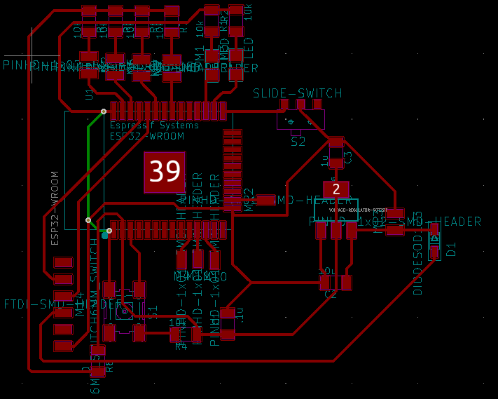
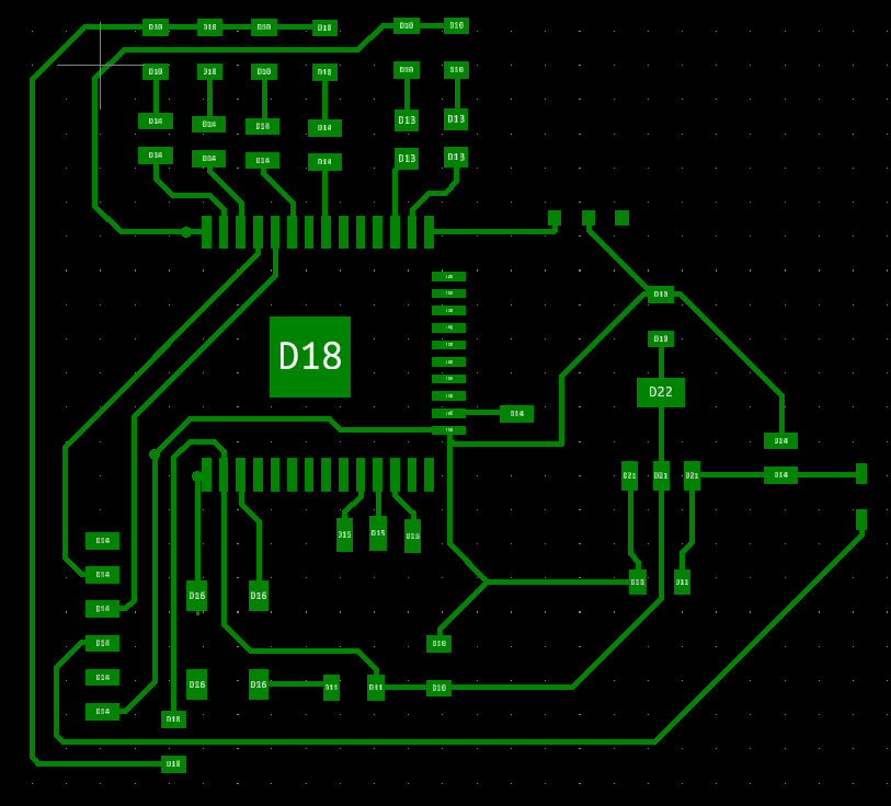
You'll notice that this board design seems similar from Week 7 - I cut two boards that week, but only built out one of them. And that is on purpose as this is all building towards my final project. However, at that stage, I had a lot of bugs to figure out. In this week, I will be testing in order to verify before I leave campus.
One of the biggest challenges will be connecteing both ESP32s wirelessly. However, I was smart enough to leave a few pins on the ESP32 connected to pads in case I needed them for later or I want to connect in via wires.
On that theme of advancin my final project, I knew that I needed an input method to control the motors for my RC car, so after some brainstorming I wanted to use flex resistors. In this method, I would put the flex resistors into a glove to be able to measure the bend in an individual hand's fingers to ascertain how fast the motors should or should not be spinning relative to the resistance given by the flex resistor in that bend. The goal was to control speed, however, I found out that I would not be able to use flex resistors. Thus, I needed a new method.
I could not use flex resistors as they were not in the Fab Lab inventory and would not be added as the staff considered them relatively expensive (~$10/each) with varying results. In brainstorming for new ideas, I had to expound on what specific capabilities I wanted to be able to transmit. Maybe, I wanted to transmit speed to motor, maybe I wanted to transmit turns, or maybe I wanted to transmit something else. In either case, it was good to take time and think deeper about what information I wanted transmitted. At the end, I realized the most important thing to transmit is motor on and off directions so that I could drive forward, left, right, and reverse. If I had time at the end I would transmit speed in another manner such as adding a pinout as I did have that option. That is when I thought back to a prior project in which I was controlling LEDs via touch motions. I realized I could apply parts of that project here. I looked back on my previous project, took the ideas that were useful to my specific project and built off of them to make an improved glove that I could use to easily provide inputs to the ESP32 and to the car.
The goal was to build a glove that has copper plates in between the fingers. These copper connections would complete a circuit and connect to ESP32 input ports. When the fingers touch the ESP32 will read the completed circuit and output a high signal to the next ESP32 wirelessly. However, I will save those details for a week when we do bluetooth/Wi-Fi connections. Hopefully, I can build this glove and also use it for the final project!
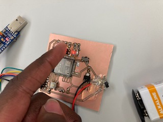
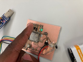
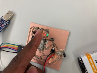
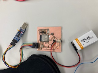
In the photos above, you'll notice that the LEDs light up according to which pin is touched.
Originally, the point of the LEDs was to verify that the signals were working properly. However, I forgot that I would need 3 LEDs and not 2. I forgot that while with 2 LEDs I can achive 4 states, but one of the states is off. Iterating in a hurry will cost you like this. However, this was not too much of a problem because I also thought of just using 1 LED to blink whenever a circuit has been completed. So, I simply repeated one state twice. In a future week, I may connect the LEDs to verify if the signals have been sent wirelessly correctly and not just internally. However, this would only be necessary if I need to debug, if the signals don't seem to be received.
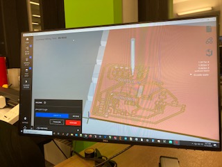
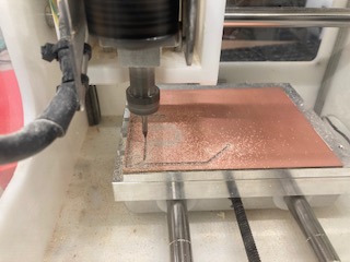
Getting ahead of myself, I was also successful in making the board wireless, in terms of power, for my final project.
This aspect was not to complex. All I needed was to connect the terminals of the battery to the ground and power lines on my board. Importantly, I put a diode in place to stop any volatage from going into my laptop, if I forget to remove the battery and plug it into my laptop simultaneously. As a fun fact, I cannot power any ESP32 board from my laptop as it sucks too much power. Thus, my only ability to run the board is from battery power. This board does not consume to much power luckily. I thought about plugging it into a wall, but I am not too convinced on this aspect since while a wall does output 12V it is 12 RMS which puts the voltage at almost twice rating of a 9V battery.
View my code to turn on and off a red and green LED here
View Week 8's group assignment here
VROOM
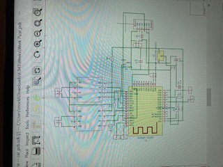
For this week, I decided to use this week in order to advance on my final project. I knew that I needed an output method to control the motors for my RC car. For reference, I spent 1-2 weeks on this board to get it working properly. My experience on this board paveed the way for a relatively smooth rest of my Final Project.


You'll notice that this board design seems similar from Week 7. And that is on purpose as this is all building towards my final project. However, at that stage, I had a lot of bugs to figure out. In this week, I will be testing in order to verify before I leave campus.
I know one of the biggest challenges will be connecteing both ESP32s wirelessly. However, I was smart enough to leave a few pins on the ESP32 connected to pads in case I needed them for later or I want to connect in via wires. However, we will get into how I get the two ESP32s communicating in the week where we discuss Networkinga nd Communication.
In the photos below, you'll see my various prototyping before the fourth and final board.
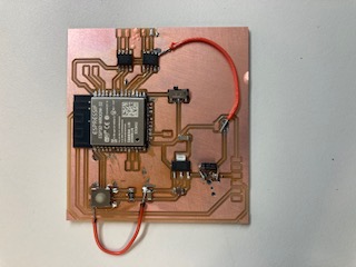
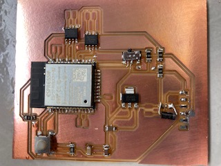
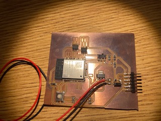
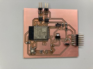
As a side note, you may realize that this sections seems familar and that is because it is! I combined weeks 7 and 9, before I knew output devices was a specific week. I didn't copy any of the text from week 7, instead I take a deeper dive into some of my problems.
I had numerous problems with all of the boards preceding the fourth and final board. In the first board, I spent an hour before I realized the ESP pins correspond exactly to the pins listed in its schematic and there is no pin conversion necessary. Mowever, the traces were thin, and I did not feel comfortable leaving it as such as I had done extensive work on the board and had to jump various wires to make sure all the connections were connected. I didn't even try to turn this board on as I was that insecure in its ability to work. To shine more light on the situation, I realized one ground connection was never made, and that it would be easier to recut the board than to finnagle a wire in place. The design rules that I put into my KiCAD didn't seem to apply automatically, so I had to go in manually to ensure that each trace was bigger than the default ~9.85 tho it was set to. Ideally, I try to aim for traces bigger than 15 thou. For power electronics, the bigger the better.
In the second case, I spent an hour struggling to realize why the pins were not turning on or off, before I reealized I had done everything else correctly. The true problem I was encountering was that I had not set the pins to be INPUTs or OUTPUTs :/ talk about embarrasing! Once I had done this small task, programming the board was still a struggle as the ESP32 can only be programmed on the 5V instead of the 3V3 on the programmer chip. I spent a little longer on this than I should have. The ESP throught "packet conent not received." Once I realized this I was thrilled that everything seemed on track. However, I was still not satisfied by the trace width as it did not automatically transfer when I cut the board. This was because of another misunderstanding in KiCAD. For lines already drawn, you have to redraw them in the correct trace width, it doesn't automatically carry over. Thus, even though the board was programmable and could run the motors, I cut again starting my real troubles.
In my third board, I realized how - ironically - lucky I had been getting up until that point. I spent 3 lab days trying to debug short circuits in my circuit. I spent roughly 1 of those 3 days wondering why my circuit wasn't working and the rest of those 2 days trying to fix it. My problem arose from using solder paste to put on the ESP32. In all of my boards before this one, solder paste did not give me any problems. However, like all things - you never have problems until you do. And, my problems were bad. I had over 3 shorts occuring between the ESP and the H-bridge. On the ESP, there was a short between the 3V3 and Ground and another between the output pins to the H-bridge. On the H-bridge there was one on the ouputs and inputs. Life was not good at this point! Funny enough, I thought it was the button on circuit shorting everything. I probably took of the button 5 times with hot air. However, I did learn from this experience. I definitely got better at hot air soldering and soldering with an iron and how to properly put on pieces. When you have that many small pins, hot air soldering doesn't save you that much time at least when you have to revisit your work like I did.
In my fourth and final board, I did not hot air soldering on any part and instead went back to basics and soldered with an iron tip. In truth, it propbably took the same amount of time to solder all the parts. Definiely less when you count the amount of time I spend debugging. In this method, I was also able to methodically verify there were no shorts or any misshaps. I made sure all my ESP32 pins were discountinous and nothing else went ary. Et voila. My circuit worked the first time around with no problems!
Here is my code for the week in picture format. It is nothing to complex. I simiply want to turn on the motor and go! VROOM!


View my code to turn on a motor here
View Week 9's group assignment here
The Time is NOW
For this week, I decided to use this week in order to advance on my final project. I knew that I needed an output method to communicate wirelessly between the two ESP32s. Thus, I investigated numerous methods exploring different WiFi and bluetooth applications of how I could do this. The method I would eventually end up using is ESP-NOW.
It is worth mentioning I have a decent amount of experience in this domain. I have taken numerous classes on this topic (6.08 is the most relevant for this content) and both of my internships (General Dynamics and GreenWatch) were involving wireless communication. The communication protcols for the internships would be way to beefy for a project of this size, but are worth mentioning: Creating access points and using LoRa. I will hit on creating access points later and will voice my thoughts on LoRa now. LoRa (Long Range) is an interesting concept, when I was working on its implementation, the protocol was relatively new - causing me many headaches as I had to struggle through distinct problems on my own. However, for truly long range communications and projects having greater computation ability, I whole-heartedly recommend it. For 6.08, I considered using a similar setup, accessing to an external server to store and retrieve information, but in my power estimations, I realized that my project is already power hungry and using such a protocol would eat the few mAh I have on a 9V battery. I, also, realized that I did not need to store or retrieve information, and more importantly, I didn't have a server to connect too. Thus, I thought it more apropos to connect the two ESPs directly together, wirelessly of course.


Now that I finally had all the boards for my final project. The only thing left to do for programming was to program them to talk together. Initially, I wanted to do Bluetooth as I could connect it to my phone if anything went wrong with the receiver board. However, I reasoned either go big or go home, so I aimed for a way for both of them to talk, obviating my phone. While, the two devices could talk via Bluetooth, I reasoned that it may not be the best option as there are other more robust better documented tutorials for WiFi-based applications. Due to the fact, that I had limited experience using Bluetooth in this domain and my knowledge of WiFi-based applications, I decided to use a more WiFi-based process even though it was more power hungry.
Initially, I wanted to set up the ESP32 on my glove as an access point and the ESP32 on the car as a client device. However, I was having issues with numerous things. I had two WiFi libraries that conflicted and the library I downloaded specific to this application was throwing an error that xTaskUniversal(....) was not found. I looked up both errors and I was able to resolve the WiFi error, but not the xTaskUniversal error.
For the WiFi error, many of the answeres involved renaming the directory as the problem arises from there being a generic WiFi library and a WiFi library specific to the ESP32. I tried renaming the ESP32 library, however, I was met with limited success as it threw more errrors. In the end, I reasoned that it would probably be more efficient if I deleted the generic library as I could always get it back, and in this moment in time, I did not need it. Interestingly enough, when I was tackling my other problem, I redownloaded the Arduino IDE and the WiFi error came back as it is auto installed with the Arduino IDE proving my point that I can always get it back.
For the other task, I was not able to solve it. I decided to switch to ESP-NOW as it was more documented for my specific use than setting an ESP32 as client to connect to another ESP32 as an access point. However, the solutions to this error did not make sense. It said to update ini files, but I did not have Microsoft Visual Studio. The error arose since the creator of that library did not utilize version control and pushed it onto the user. Essentially, if you to ever use the library AsyncWebServer than you need to make sure everthing relevant is NOT up to date as the library is not compatible with newer updates of Arduino.

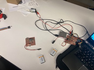
Above, you will see an image from my first test. It may not look like much, but this was the start of the end for my final project. Somehow, it worked on the first try and for that I thank God. It was all completely wireless and worked reliably - with fresh batteries.
I really appreciate ESP-NOW. It fulfills my need to drive a motor from simply touching a pin on another disconnected board from the motors. ESP-NOW works by encoding the MAC address of the receiver unit. It is a two way communication device, so you can easily verify that the data was received. It is deceptively simple which I appreciate.
View my code at the end
View my code for the controller circuit here
View my code for the motors here
View Week 10's group assignment here
Let's Interface
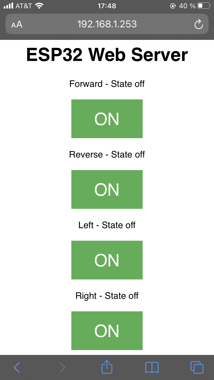
This week presented an interesting challenge. At the point in time when I began this week, I was already done with my final project, so any additional work on my RC car would be a step backwards. However, I didn't not want to not incorporate it into my final project since I like building cool, interesting gadgets. Thus, I decided take a turn on my implementation.
To make something independent that can also be incorporated into my final project, I thought of a few applications to make. The three ideas were all ESP32 IP address based. The three ideas were as following: a webapp to view the ESP32 camera to remotely see where the car is going, a webapp to turn on and off LEDs on the controller circuit board, and a webapp to directly control the motors on my RC car - final project. In deciding which to do, I had my Old El Paso taco revelation, "por que no los dos," and I decided to do all three of them. However for the purposes of documentation, I will go over all of them, but only detail 2 of them due to upcoming exams and time constraints. However, detailing 1 is enough for the purposes of documentation.
First I want to give an overview of how I was able to do what I did and then I will get into the specifics for each project. Really, all of them follow a similar process. The most disimilar is setting up the camera. I should note that I have had experience setting up webapps on ESP32s via previous internships and interest. All of this can be simply done through the ESP32's WiFi library. In that way you can set up a webpage as beautiful or as minimalistically as you please. You do this by writing HTML int the Arduino code. You can probably do CSS and maybe JQuery, but I haven't tried this just yet. Realistically, Anything in CSS can be replicated in HTML, just with more work. But for my purposes, my website will be minimal - just something for pushing buttons for LEDs, motors, and the like. Please enjoy screenshots of my Arduino code.
For my first documented interface app, I actually had the idea of doing this, if my controller circuit was not able to connect well with my motor PCB board. However, this was not an issue for me, so I shelved this side project. However, I am taking it off the shelf and dusting it off, so that I can use it for this week. This project flows pretty similar to how the LED buttons will funtion, however, we will get there in time. I used my code from ESP NOW as a template, but I had to make some critical changes so that I would avoid potential errors. One of the biggest worries would be that I would damage the motors in some aspect since each motor pin is connected to its own H-bridge output terminal. The fear here was that I was not quite sure how these particular motors worked so I did not know if both pins being high would have some effect. I do not imagine it would, but in the unfortunate case that I did find out, I figured it would be better to obviate discovering. More importantly, if both motors are high then the car won't move! Thus, the changes I made were that only one button could be active at any given point because if both right and left are on then the car would be going straight and that is not what I intend and neither does the ESP NOW code work like that either. I should remind you that the car is zero turn - ie when only one wheel is on it turns in that direction - so that is why the car would go straight in this implementation. There are a few other car drive train implementations that I thought about, but in either case I would more than likely see some error and besides it's not good code/functional implentation.
For my second documentation example, I made an app to control the two LEDs - green and red - on my controller circuit. It's a nice simple example that I can demo at any time. Specifically becasue it can be a pain to access the PCB board on my car as everything is getting fit into place. This was probably the easiest to implement as there are a plethora of examples online with one or two LEDs and lighting and LED is the quintissential Hello World when it comes to crossing programming and electical engineering skills together. Thus, this example follows the example from above where I edited the code from my motors.
Lastly, I made a webapp to see what my car sees. I had actually planned to do this with time pending, and luckily there was a week for me to fulfill this objective. This one was not as complicated as I expected it to be. Funny enough Anthony shipped it to me in the same box as my clank. Luckily there are a bunch of ESP32 cam mod tutorials on how to stream the video from the camera on the ESP32 webapp. However, as noted from earlier, I will demo the code here, but I will not be able to show any pictures or videos as I did not have enough time between then and final presentations to get a working product due to final exam preparations and other time constraints. With this item, my final project is truly complete. Unfortunately, I am not sure if I have enough parts for the cam mod as it has pins and I do not know if I have enough pinholders to put into onto a PCB board, but we will see. Maybe I will get some next semester - if I am allowed back onto MIT campus.


Not that these are needed, but I will include the schematics here. I am not including a schematic for the ESP cam mod, because you can get away without using a pcb, if you are clever.
View my code to turn the motors via a webapp here
View my code to turn a red and green LED through a webapp here
View my code to stream via the ESP cam module here
View Week 11's group assignment here
I Love You 3000
For my final project, I've gone through a few iterations. Initially, I wanted it to build off one of my prior capstone classes such as 6.101 - analog labrotory. Partly, since I was not able to make the PCB in the class due to time constraints. In that class, I made a two way radio complete with a battery charger and solar panel - everything was made from basic IC parts there were no IC circuits used. You can go here if you want to check out that project and find my project labeled AM Radio Transmission. However, after discussing my project with staff, I realized it may not be the best use of resources in this class. Since you need to integrate a microcontroller, that defeats the purpose of sending AM or FM radio signals since you can just open a Wi-Fi, Bluetooth, or another communication protocol via the MCC to communicate with another device. Thus, I changed focus.
Going off the theme of building off of work from prior capstones, I thought back to my final project in 6.111 - digital labrotories. In that class I made a Human Computer Interface device where you hand effectively turns into a mouse for a computer or laptop. I included the video above. However, here is a link to that project! Navigate to the project called EDITH to see.
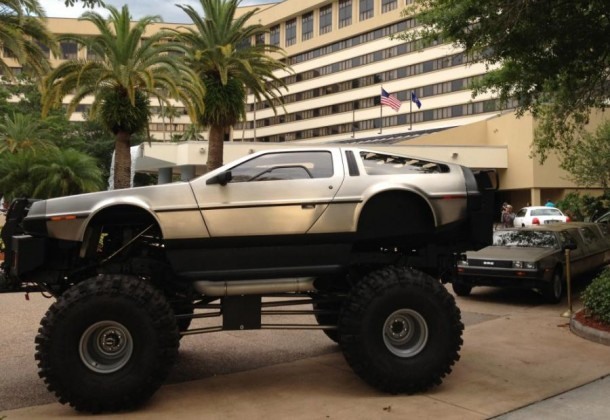
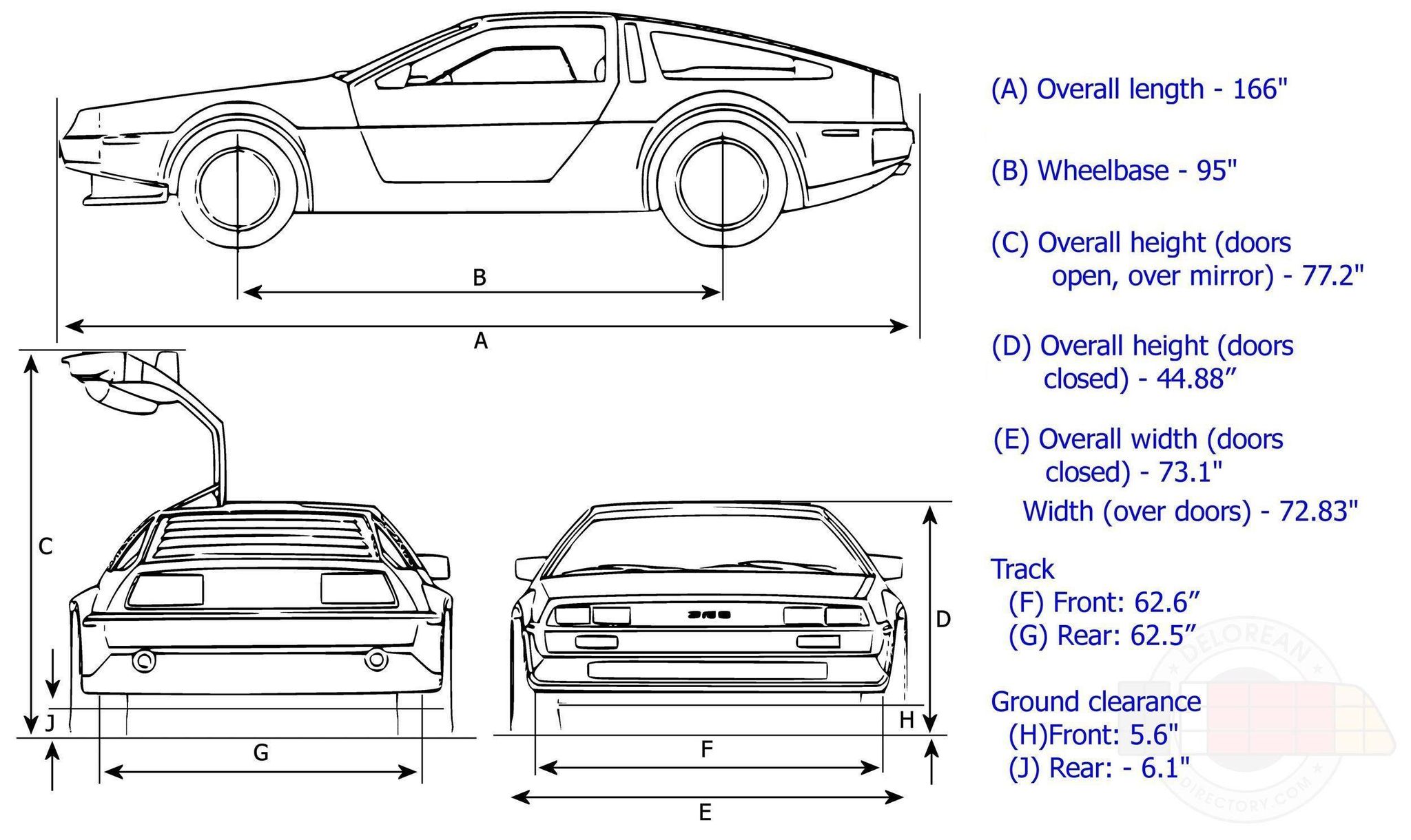
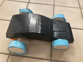
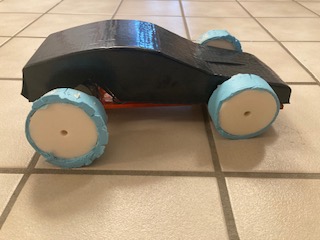
Thus, I thought it would be cool to build an RC car. I remember wanting one when I was younger and never getting one, so what better opportunity than to make my own! Also, I thought it would be MIT relevant to make it in the shape of a Dolrean. I modeled the dimensions after one. It looked better in the CAD file, but it doesn't look too disimilar to one and I can also post process it to get the Back to the Future vibe. As another note, I remember in high school when I took a CAD class, I designed a RC car, without the electronics and a terribly inferior turning system. So, this was a way to prove that I could do everything now that I couldn't before. As a side note, I managed to use every machine in the EDS, even the thermoformer - a bonus tool - minus the vinyl cutter, which was my favorite tool. If there were more time, I would have used the vinyle cutter to decale the thermo shell to make it look more like the Delorean from back to the future. Moreover, my project cost nothing as everything came from the lab and parts available.
At the end of the project, I realized that this RC car if it had a camera could fulfill something I wanted to do at the beginning of the class, but later forgot - a surveillance drone. Technically, this does count as a drone since it can be autonmous, but doesn't fly. But anyway, this would be a great way to keep track of crops if a field without having to move very far, if that is a concern. The camera will be done post final project, since I didn't promise that originally, but would love to incorporate it.
As a final side note before I get into my project, if you feel any detail is missing in this section of my website, check out the preceding weeks. There is a good chance I covered it there and not here. My final project took over 5 weeks, and even though I tried to document as I went, I put more emphasis on the week due than this section. However, that being said I attempted to make this section as complete as possible.
Consequently, I thought it would be unique if I could make an RC car that you control via how much you bend your fingers. However, as you will see in Week 7 Input Devices, flex resistors were not an option as the class would not be able to provide them due to their relative high expense and expected poor performance. Thus, I went back to the drawing board. Since, I still wanted to be able to control all of this from a glove, I thought it would be novel if I could devise the glove to be improved on my design from 6.111. Instead of touching your thumb to the base of your fingers, that can be awkward, I would put copper pads between the individual fingers so that when two fingers touched that would correspond to a specific movement such as forward, reverse, left, and right. I planned, if I had time, I would also do capacitive sensing to change the speed of the motors between a low, medium, and high setting. However, in our shortened semseter, the EDS did not have workable fabric, and I did not have time. Thus, I will rely on touching the pins together on my board. It is surprisingly ergo-dynamic - holding it in one and and touching the pins togher with your finger. This might actually be a more natural movement than my glove idea. However, let us get into the nitty gritty oh how I made the circuit.
One of the biggest challanges in this project and class was PCB milling. Builing the clank was fun and exciting. Surprisingly, it worked the first time around when I turned it on. With things like these, I almost never expect it to work the first time you turn on the power. However, the trouble would come later ;). And, that trouble came in the form of breaking bits. In total, I think I broke 2 or 3, but it was a good learning experience for me and the class. Originally, I was a little perplexed on why my bits broke, but it boiled down to a collection of things: Flattening the bed, watching the spindle orientation, zeroing the tool correctly, and toolpath speed and depth per cut. The bits broke for maybe one or a collection of these reasons - that would be my best guess. In the build, I think these things weren't emphasized in their ture importance, but they can really jam you up down the road. For toolpath speed and depth of cut, these things should be automatically resolved by Anthony's, Jake's, and Neil's tool optimization and MODS edits. However, for the bed flattening, spindle direction, and tool zeroing, the individual should be as cognizant of these things as possible. While I was still on campus, I used a copper plate to flatten, so that the copper plate would be my sacrificial layer and I could preserve the plastic base until I went home and would only need to flatten the bed once more in perpetuity as I do not expect to move the clank any further. For zeroing, I did it the way Jake recommended in the video, but I think it was just a hair to far down and eventually broke due to that. Instead, I use a method Anthony showed me where I put the bit into an untightened spindle and place the tip on the bed and lower the clank onto the bit, so that it is zeroed by the tool instead of the clank. It is a perfect fit.Another thing to keep in mind is that the spindle is set to 7,000 for spindle speed, however, during cuts you need to increase it to 10,000. It may not make a difference now with the optimizations, but it will definitely help your cut.


The PCBs are pretty well covered from Weeks 7 to 9, but it is still mentioning that perfecting the art of making relatively large scale PCBs in terms on number of joints soldered took me a while. There are not too many components and you could say that I am undershooting the programming capacity for the ESP32, but I am not too woried about those details. I use as many components as I need and not 1 more. To me, elegant engineering and design is the one that only uses as many compenents as necessary. I already had experience with the ESP32 and knew its capabilities and time was not on my side. It is better to go with the enemy you know than the one you don't. One could argue that I could achieve better power optimization with an ATtiny chip and a 433MHz chip, but I am not truly familiar with either. In a worst case scenario, I spend an extra week, figuring out how to work them. That one week extra week would mean that I cut out other parts of my Final Project. In this case, thermo forming the shell of the car. In short, I optimized to integrate as many aspects of this class as possible by not optimizing for specific aspects of this project. I want you the reader to know that. It is definitely possible to improve off of this project. I had four weeks from inception to conclusion. If you have eight weeks or start from what I have already built then you can go miles more than me in four weeks. I hope, time permitting, that after this class, I can keep iterating on my car and clean it up to give it a more polished, ready-to-sell stylization. Enjoy the rest of this article as I avoid giving a thesis and aim for a more entertaining, quasi-cookbook run down of how things went.
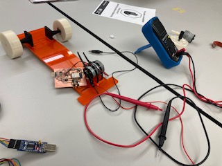
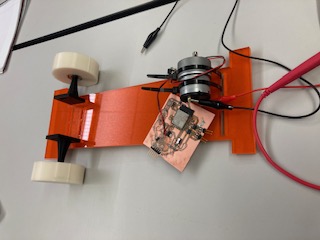
Now that I have gotten some salient information out of the way and given you the inspiration for the project, I want to talk about how I will go through aspeects of this project. First, I will talk about the glove, then I will talk about the car, and lastly, I will address any other lingering questions such as connectivity and programming. All of this is in no specific order. In the glove section, I will address the PCB creation process, soldering, and debugging. In the car section, I will address the the drive traing, motors, the wheels and support, the base, and the shell. In the programming and connectivity section, I will address how I programmed the boards and how I cnnected them together through a relatively new ESP wireless protocol, ESP-NOW.
Something worth mentioning is that whenever I tried to run the ESP32 from my laptop, I sometimes encountered brown outs, like the board for the ESP32 was trying to draw too much power from my laptop. However, I didn't think too much of this since I also had the battery power option. But, near the end other people asked me about this since they knew I was using the ESP32 and they were trying to use it and encountering similar difficulties. I wish I had explored it. Originally, I thought it was the motors, but I suspect it to be the voltage regulator. However, I am not sure. I will try to investigate now. The one thing that I did wish to add to the battery connector was an on/off switch. This way I could save battery power and leave the battery in when I am uploading code and storing it. I did use a diode to halt power flowing into my laptop, but better safe than sorry.
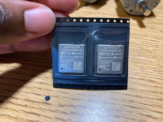
For both, boards, I used the ESP32. Consequently, the layouts are similar, the only differences are the H-bridge/motor and LED/input connectors. All parts are from stock except for the motors which the EDS was able to provide. On the motor ESP32, I used two H-bridges so that I could alternate directions the motors spin, forward and backward. On the LED ESP32 board, the LEDs were left over from a different week, but I thought it would be helpful in debugging, so I left them. However, I didn't need to debug, so I left the LEDs in their original configuration, light to specify which input is being received. On both boards, I left numerous pins to empty pads in case I needed to use them later. It did come in handy, one of my pins was outputting like it should so I used magnet wire and jumped a wired to the intended position after cutting the trace to the other pin. Overally, the boards were the central part of this project. I connected them via ESP NOW a low power WiFi protocol that is a two way message protocol via MAC addresses. Origininally, I thought I may have to connect the two boards via wires as I wasn't finding too much on Bluetooth, my first intended protocol. However, I realized go big or go home as bluetooth's reception distance is poor and connecting can be finicky. Then, I tried setting it up as a web access point, but had difficulty with a library. Finally, I gave in to looking at ESP NOW. It was a protocol that I had never heard of due to it being new. I was hesistant of it for that reason, but I am so glad that I am using it. It connects fast and works well. Look at my code, linked at the bottom, to see how it operates.
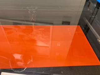
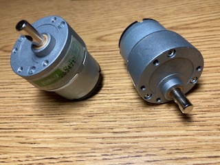
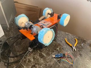
For this project, I also 3D printed and laser cut. I laser cut the board of the car as it was too big to 3D print and much faster and easier to laser cut acrylic. With the acrylic I put rectangular holes to secure the motors, the front wheels. For the PCB board, I planned to either use hot glue or double sided tape. Not too much to say there on laser cutting overall, it was a standard process. For 3D printing, I printed the front wheels, front wheel holders, back wheel axels, and back wheels. This process took a while on the nice printer in the EDS, the prusa I believe, but it was worth it as the resoultion was extremely nice. Funny enough for the axels, I somehow got the distance right for the hole between the bottom of the motor and its top. So, I didn't need to reprint the part and could place th lynch pin in perfectly, first try. But, luck always balances out.
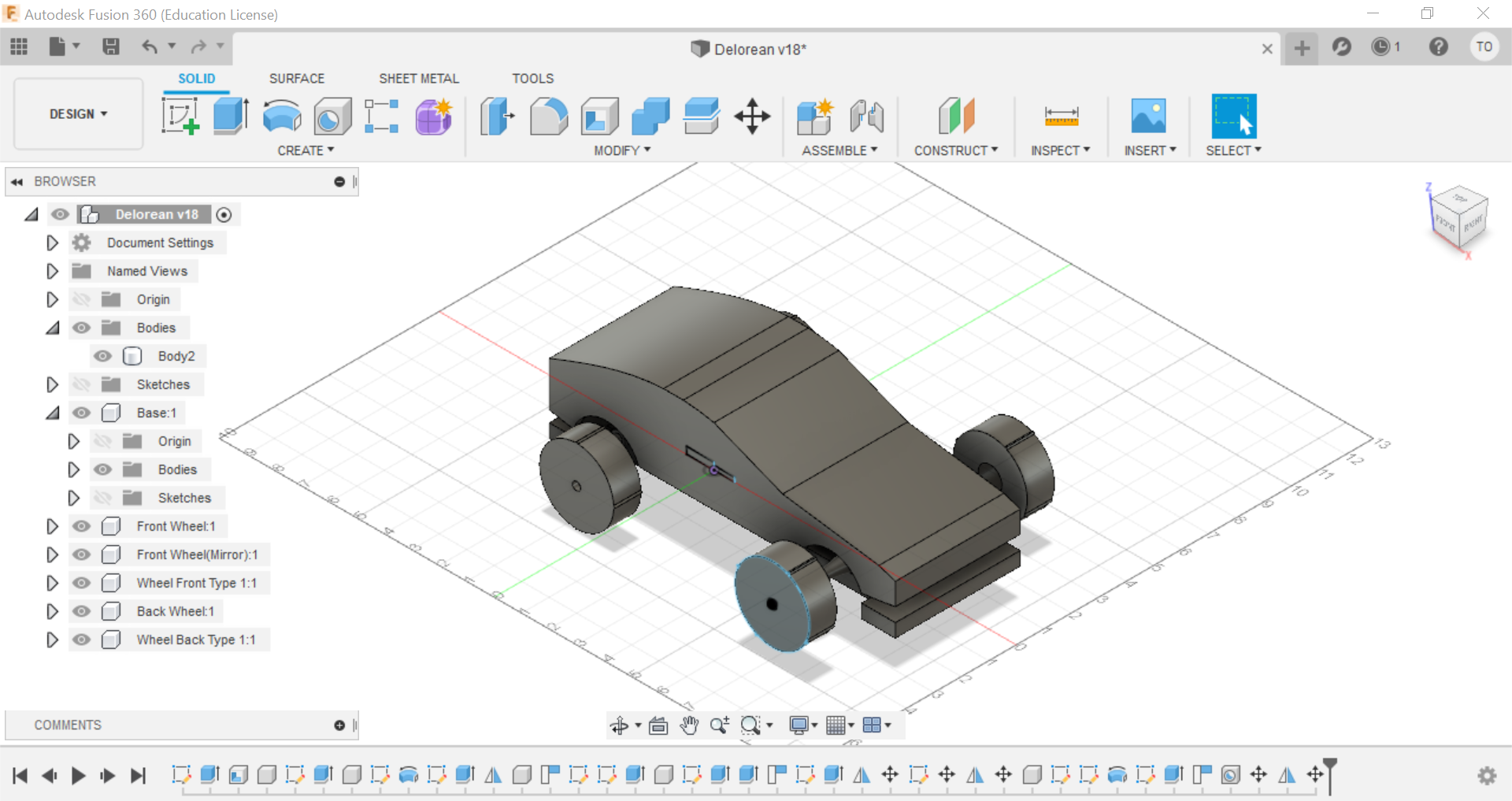
Above is my car in CAD. Additionally, I will also include my CAD files as a step file here.
Once I printed the wheels, I used exact distancing to know how big I should make the end of the axels for the back wheels and how big the holes should be for the front wheel to place a bearing, allowing free movement to spin. Admittedly, the front wheels were easy, but the back wheels were not as simple. The bearings were actually left over from the clank. Problems between the bearings and front wheel came about because I placed the bearings too deep into the wheel. Really, all I need was to make it flush in the hole and not put it all the way in the back. To reverse what I did, I used a heat gun to soften the wheel and free the bearing. After letting it cool, I placed the bearing back into the hole and made it flush.
By the end of this final project, I was swearing by hot glue,it's how I secured everything in this project so there is no woble. I'll hit on this again later.
As a funny fact, one of the connectors between my 9V battery and the connector circuit board broke 30 minutes before my final demo and my video, so I had to go into emergency surgery to resolder the connection and seal it with hot glue, so that it wouldn't fall out again. The surgery was a success!
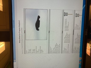
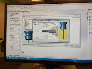
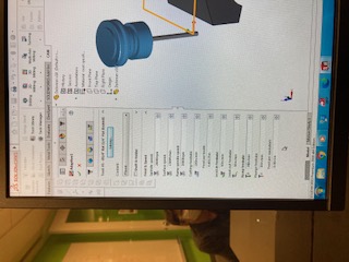

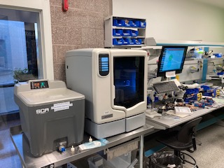
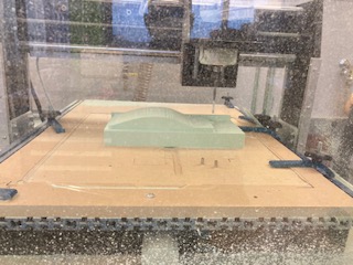
Milling the shape of the car was perhaps the most fun part of the final project. Mainly, because it meant I was done with everything that I said I would do. But, partly, because it meant I got to interact with SolidWorks CAM again. If you remember, I had some difficulties during the molding and casting week, so this was an excellent opportunity to gain more fluency for the system. In the photos above you will see feed, speed, and depth rates. I thought it would be nice to include, but they are not anything out tof the ordinary. The only thing worth mentioning is that for the mill in the EDS, my block of foam was so big that I needed every inch of the tool to get the job to only be done by the mill.
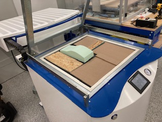
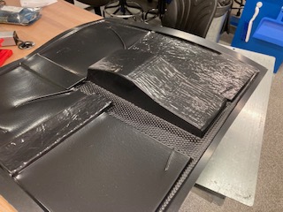
Thermoforming was also a fun, but frustrating experience. It was also a bonus machine that I got to use. As a side note, I can officially say that I used every machine in the EDS workspace. Getting back on topic, thermoforming was fun because I got to take this big, relatively in flexible piece of plastic, melt it, and then blow it up like a ballon. However, it was also frustrating because, I had to upgrade to a bigger thermoforming window, but my piece was still relatively small for that window, but inches to big for the smaller machine window. If I had a smaller window, it definitely would have come out better even with 5-10 attempts, but I am still satisfied what I was able to get from the machine. Better, in fact, since I didn't have to 3D print it meaning that it came out light and easily replaceable.
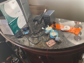

Above and below, you will see some scenes from my at home lab. I didn't have to use to many parts as I was able to complete 90% of it on-campus, but I did use the soldering station to secure wires from my motor to my board. Originally, I wanted to use alligator cables, but they were loose and to long to comfortablely put under the thermo shell. More over, I also ended up using a ton of hot glue. This wasn't in the kit, but I was able to get some from my mom who is a teacher. I used hot glue to secure the motors to the acrylic in conjunction with zip ties, I repeated these steps with a few coats/rounds of hot glue. Also, I hot glued the front wheels into their slots so that they wouldn't fall off in motion if they got too loose, and to secure the oomoo to the 3D printed plastic wheels. You could say hot glue held my project together (pun intended). Interestingly, I brought zip ties from the lab home, but I could only find one, so I managed to slip off the zip ties from the clank that was shipped home, using a technique that doesn't snap the zip tie in half.
To make my wheels slip-proof regardless of the surface, I oomoo'd the wheels, by taking a wheel and putting inside the cardboard of a roll of tape, then I poured oomoo into the hole and let it solidfy. My first try wasn't great, but I got better as it went along. I did the process six times - I had two spare wheels. Next I hotglued the oomoo onto the wheel, so that it would slip off when turning and cut off the rough edges. Honestly, the process went a lot better than I expected. However, as to be expected, the wheels with or without oomoo work best on carpet, more friction.
As a final word, I have truely enjoyed this class and have learned so much. It has actually made me want to work in a machine shop, but who knows. I hope you have enjoyed my projects over the weeks and maybe even feel compelled to replicate one! Thank you for bearing with me through my ramblings and projects!!!
View my final code for the motors here
View my code for the controller circuit here
View my code for video streaming here
