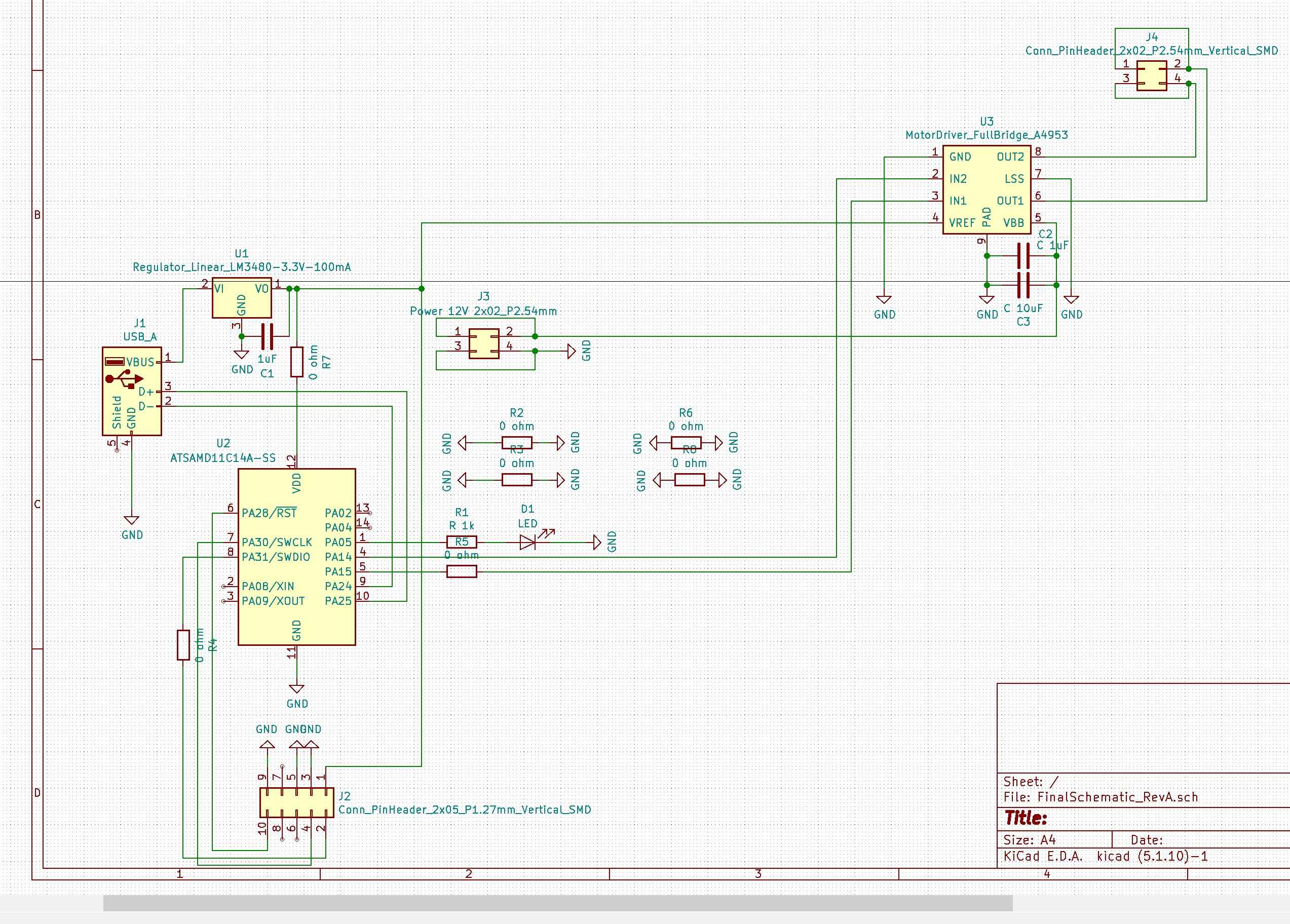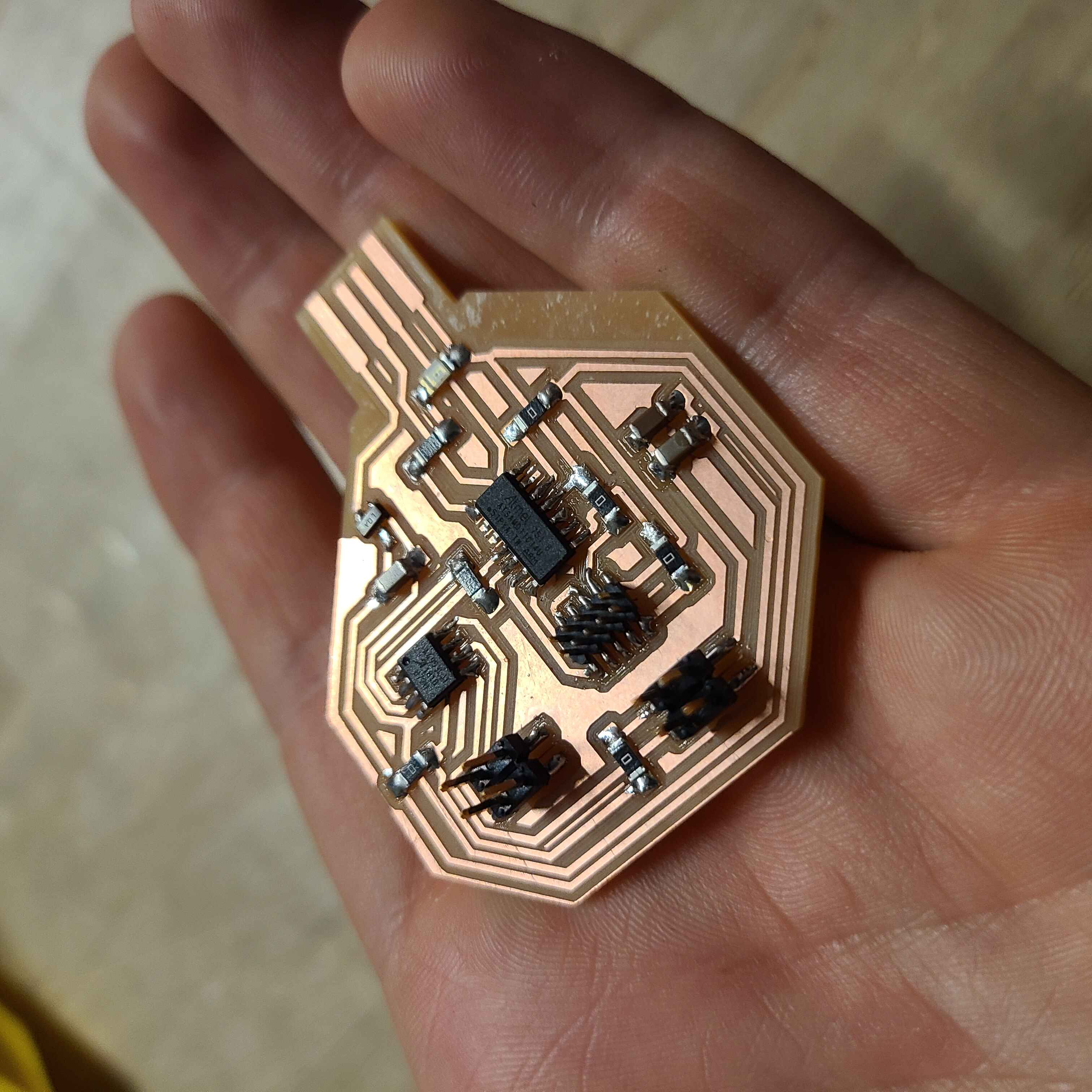
I enjoy running the traces and connecting the components but I realise this is probably the most complicated board I can make without having to cut vias. I think next time I'll have to learn how to make my boards 2D.

Some obligatory milling images...


So I did manage to get the bootloader onto my SAMD11C. I need a little bit more time to figure out how my pins are connected and whether I have made the correct assumptions when linking my MicroController with my Full Bridge and DC Motor output pins...

Update: Yes, I did make the correct assumptions!
I uploaded a simple code that makes the pump motor turn clockwise for three seconds after which it turns anticlockwise for three seconds. The code looks like this:
const int ledPin = 5;
const int in_1 = 15 ; // Pin 5 (PA15 on SAMD11C)
const int in_2 = 14 ; // Pin 4 (PA14 on SAMD11C)
void setup() {
pinMode(ledPin, OUTPUT);
pinMode (in_1, OUTPUT) ;
pinMode (in_2, OUTPUT) ;
}
void loop() {
digitalWrite(ledPin, HIGH);
digitalWrite(in_1, HIGH);
digitalWrite(in_2, LOW);
delay(3000); // wait for 3 seconds
digitalWrite(ledPin, LOW);
digitalWrite(in_1, LOW);
digitalWrite(in_2, HIGH);
delay(3000);
}
Here's the pump doing its dance:
const int in_1 = 15 ; // Pin 5 (PA15 on SAMD11C)
const int in_2 = 14 ; // Pin 4 (PA14 on SAMD11C)
void setup() {
pinMode(ledPin, OUTPUT);
pinMode (in_1, OUTPUT) ;
pinMode (in_2, OUTPUT) ;
}
void loop() {
digitalWrite(ledPin, HIGH);
digitalWrite(in_1, HIGH);
digitalWrite(in_2, LOW);
delay(3000); // wait for 3 seconds
digitalWrite(ledPin, LOW);
digitalWrite(in_1, LOW);
digitalWrite(in_2, HIGH);
delay(3000);
}