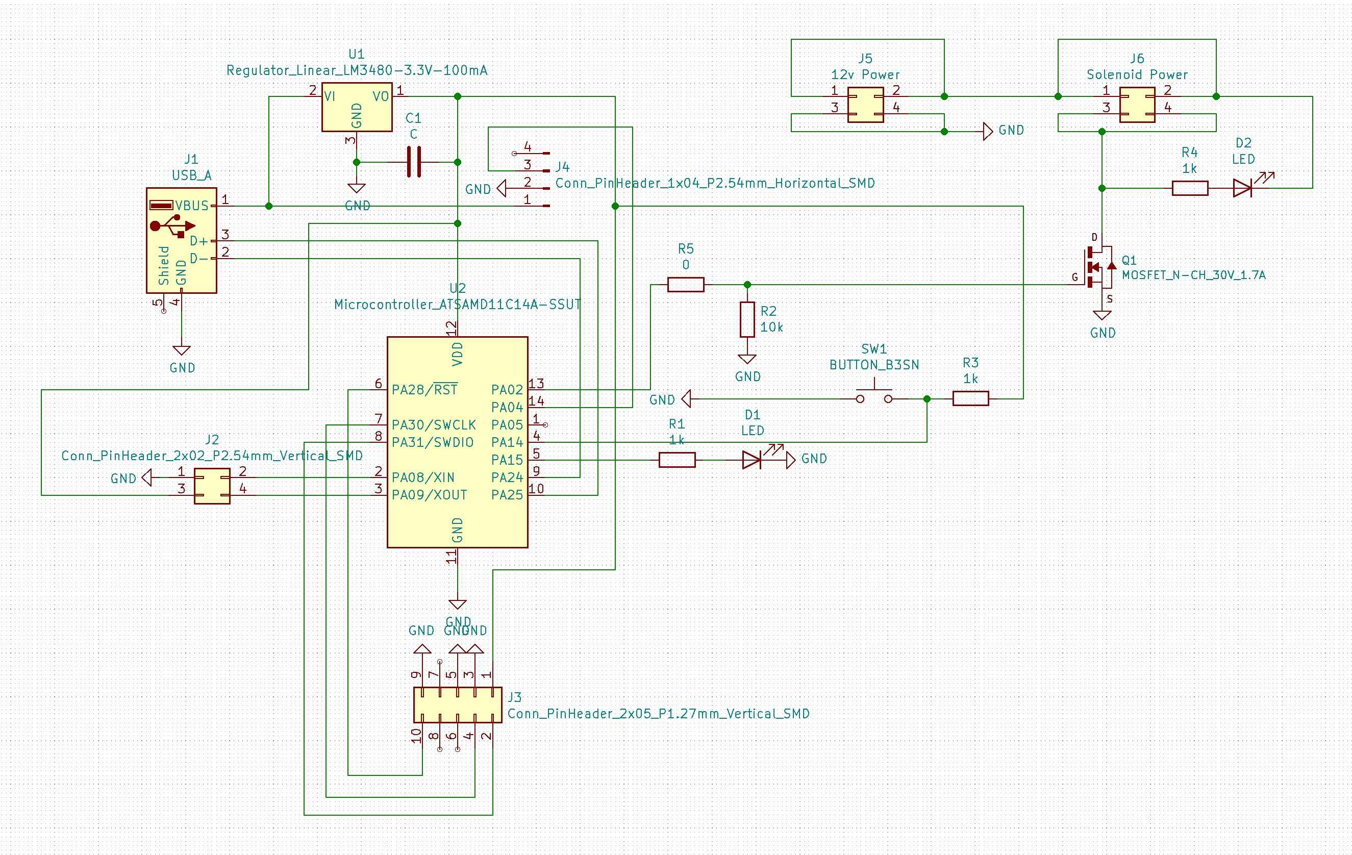
So I started with a schematic in KiCad. I initially wanted to just get the pressure reading, but figured I could add some extra functionality to my board by adding an LED, a button, a pin header for communicating with future boards and, probably the most interesting for me but also the most challenging, a 12V solenoid valve that I would later use to expel high pressure air into an actuator.
I'm going to save my future Output Devices self some writing and just talk about the solenoid here. I got the following 12V variety guy off of amazon:
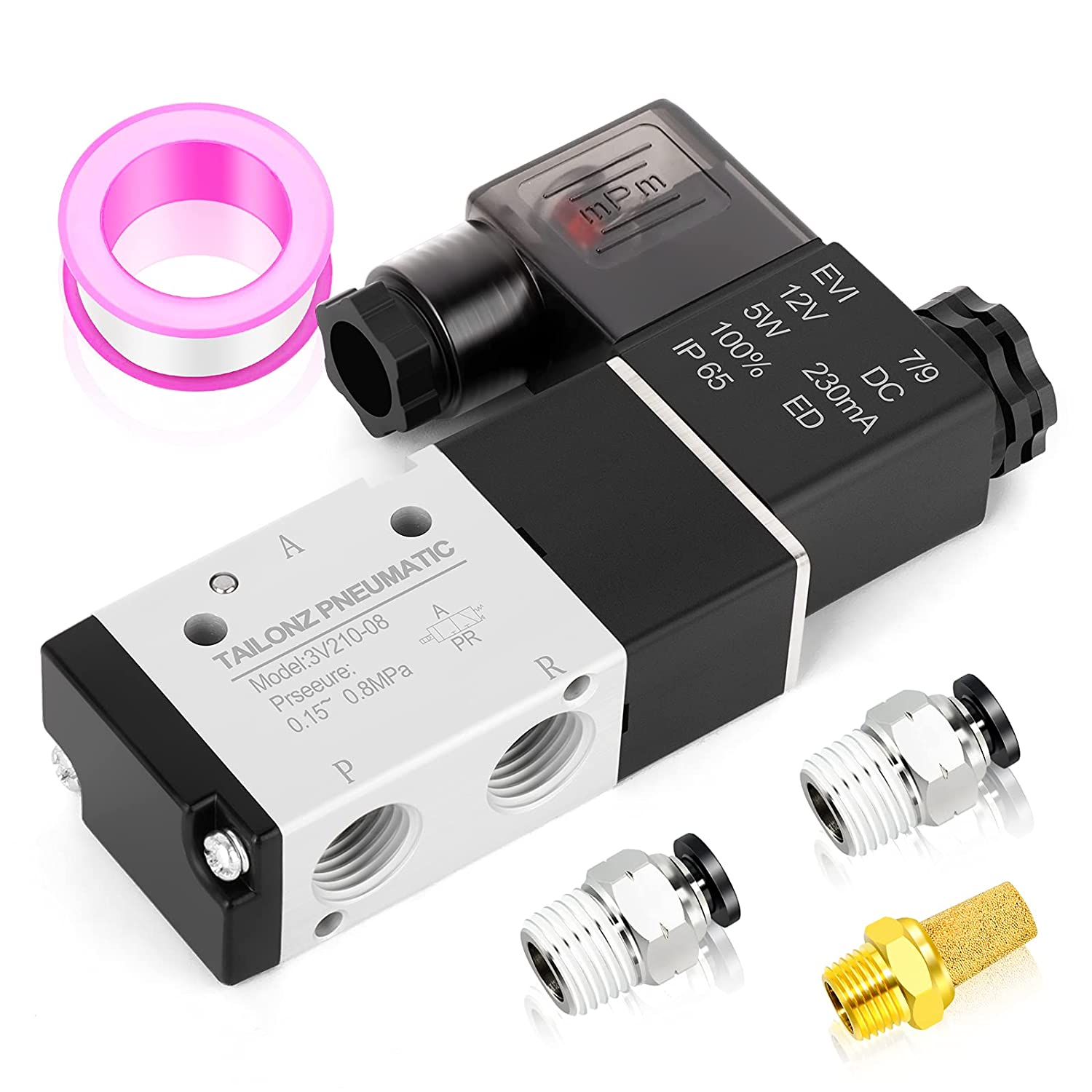
TAILONZ PNEUMATIC 1/4"NPT Solenoid Valve 3V210-08 12V/24V/110V/220V Single Coil Pilot-Operated Electric 2 Position 3 Way Connection Type
From what I understand a solenoid is a metal piston powered by an electromagnetic field. It can be used as a generic piston, an electric door latch or, in my case, a valve that allows air to build up in the inlet tubing and then be released when powered up. It also has an exhaust functionality that, when de-powered, allows the air to escape from my soft actuator effectively resetting it. This particular one only sports a red and black wires, which you can connect in whichever way you want. The only thing this valve wants to function is a kick of current.
To get my solenoid to work I needed 12V external power, a pinheader that would connect to its red and black cables, a kickback diode that would dissipate excess negative current after the power is switched off and, the most vitally, an N-Channel MOSFET.

DroneBotWorkshop on youtube
An N-Channel MOSFET has three pins; a gate, a drain and a source. The gate connects to my SAMD11C's digital pin. The drain connects to one of the cables from my solenoid. The source brings the entire thing down to gnd. Essentially a MOSFET acts a switch. When my D11C pings the gate HIGH and the gate threshold voltage is reached - less than 1V - the circuit between the drain and source closes and current is allowed to flow between the higher voltage power source, through my solenoid own to common gnd. After the voltage from my D11C is taken away (and because of some electrical wizardry that I don't actually understand) a negative current is generated that can create sparks, heat the system or do some other mischievous things and so a kickback diode is necessary to allow the current to dissipate by cycling through itself and the solenoid. As you can tell from my schematic the diode is actually reversed and that's because I don't want it to be "noticed" during normal operating times of the solenoid.
Ok with all that half-understood babble out of the way here's my arranged board:
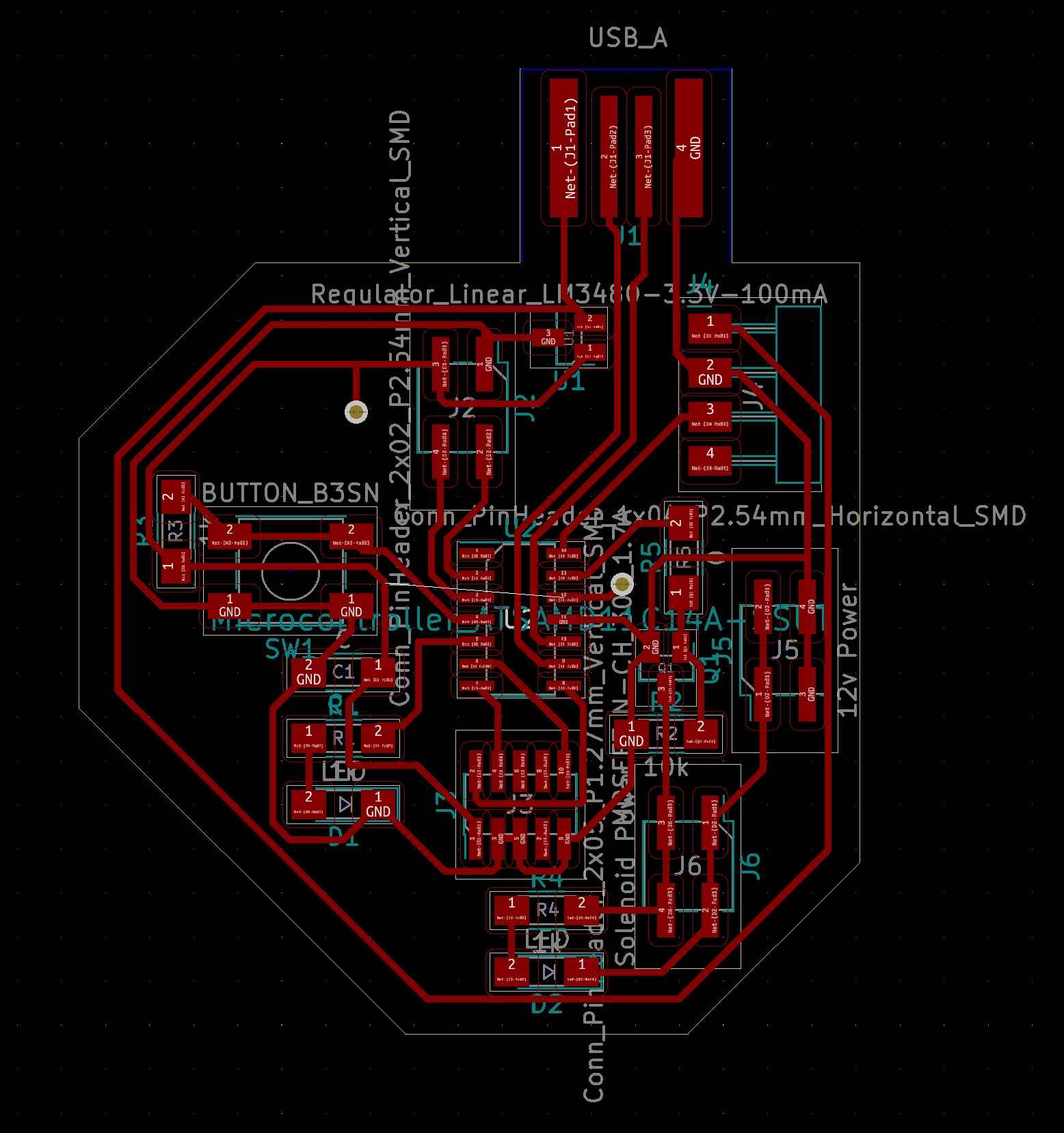
I had a way easier time arranging these traces than I expected. Maybe I'm lucky or just simply getting better. In any case I needed only one 0 ohm resistor and used two vias to connect my SAMD11C to 3.3V.
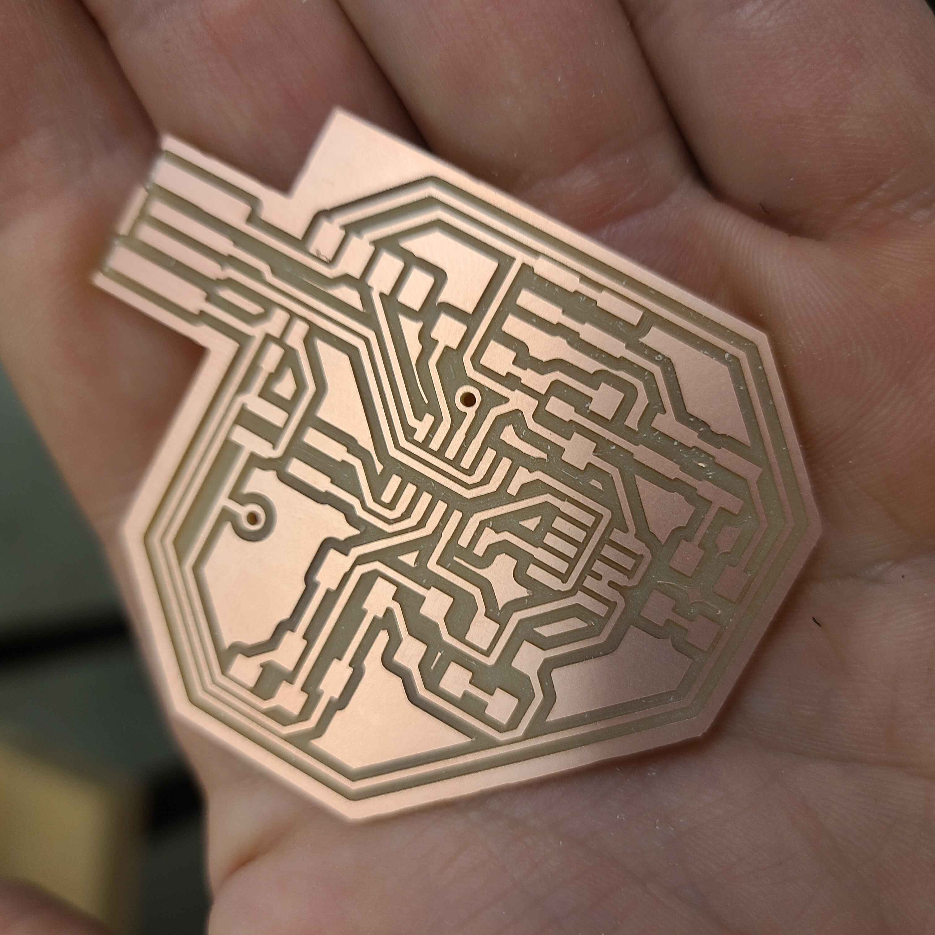
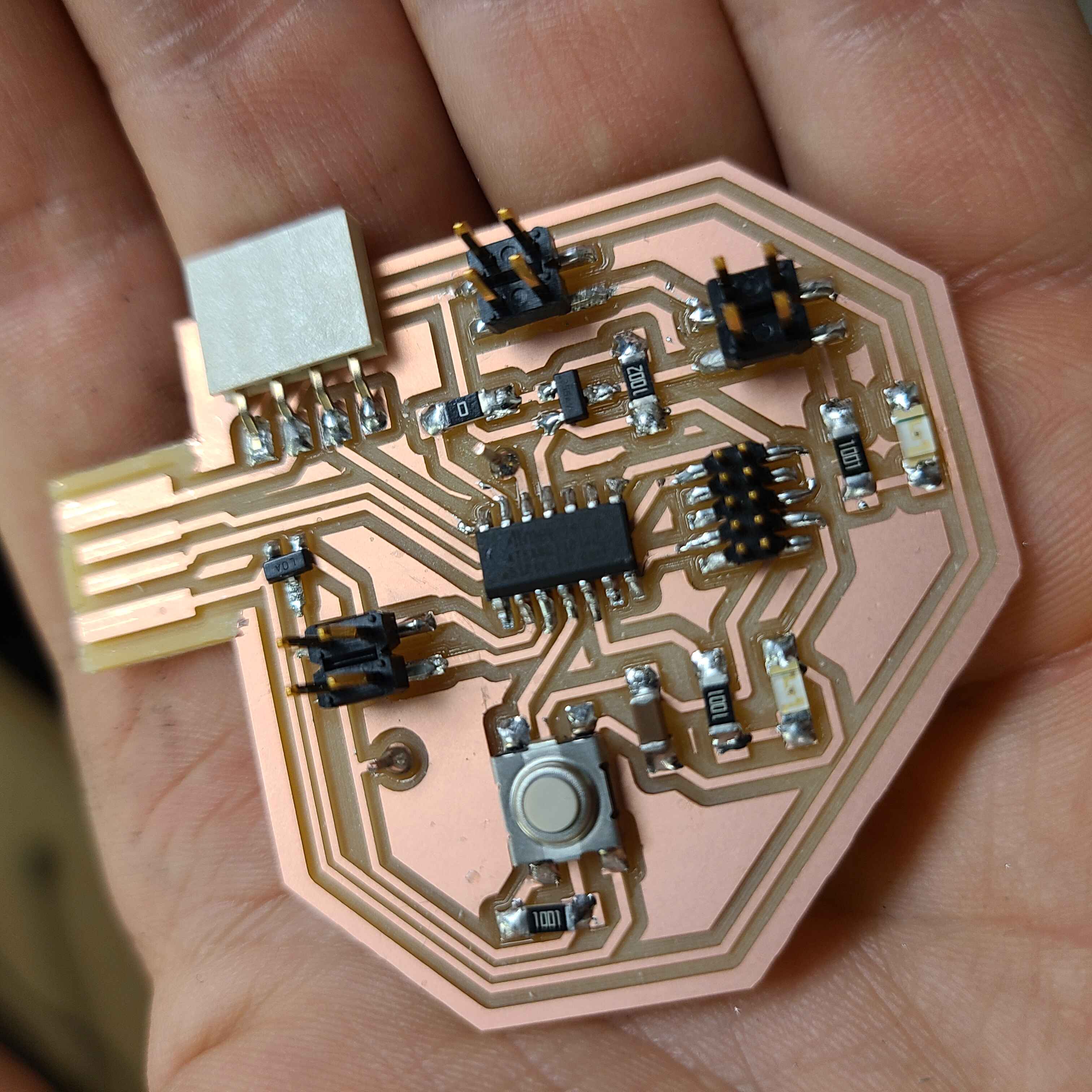
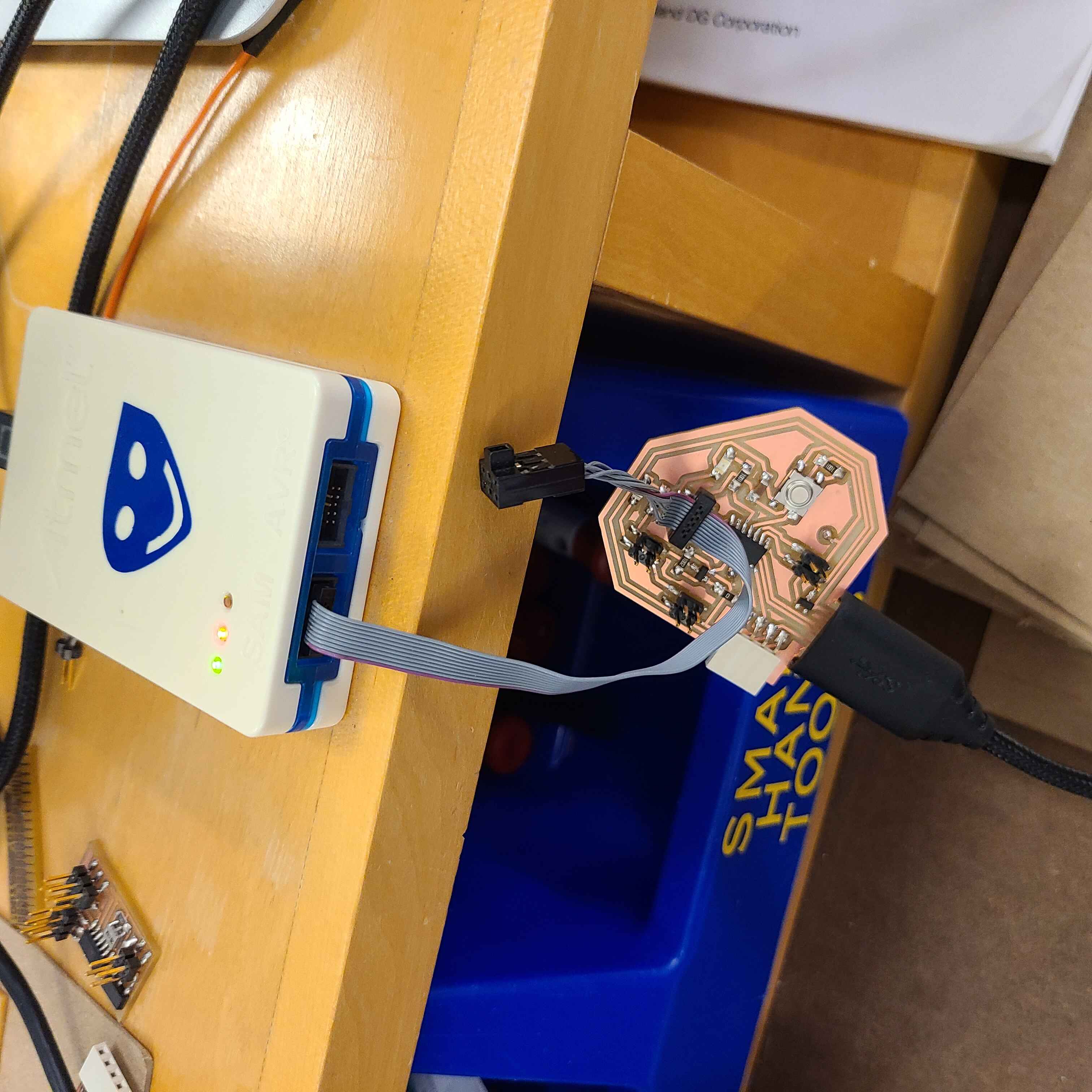
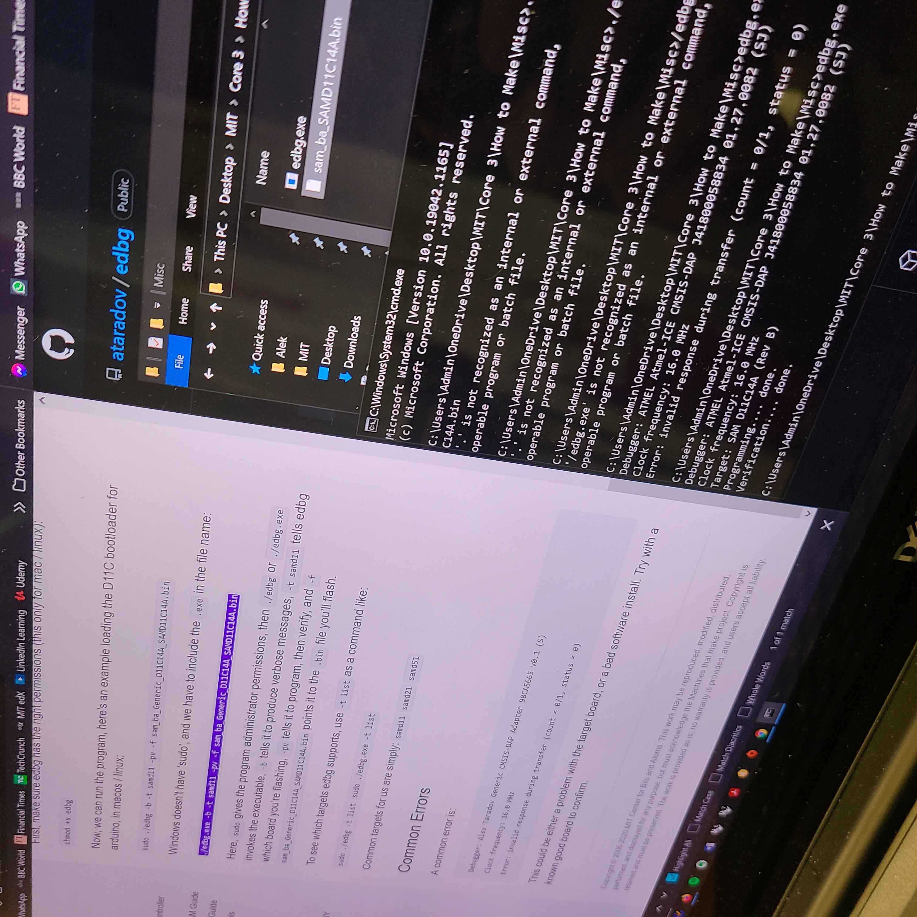
^ a quick montage of milling, stuffing and bootloading (this time via my owm laptop!)
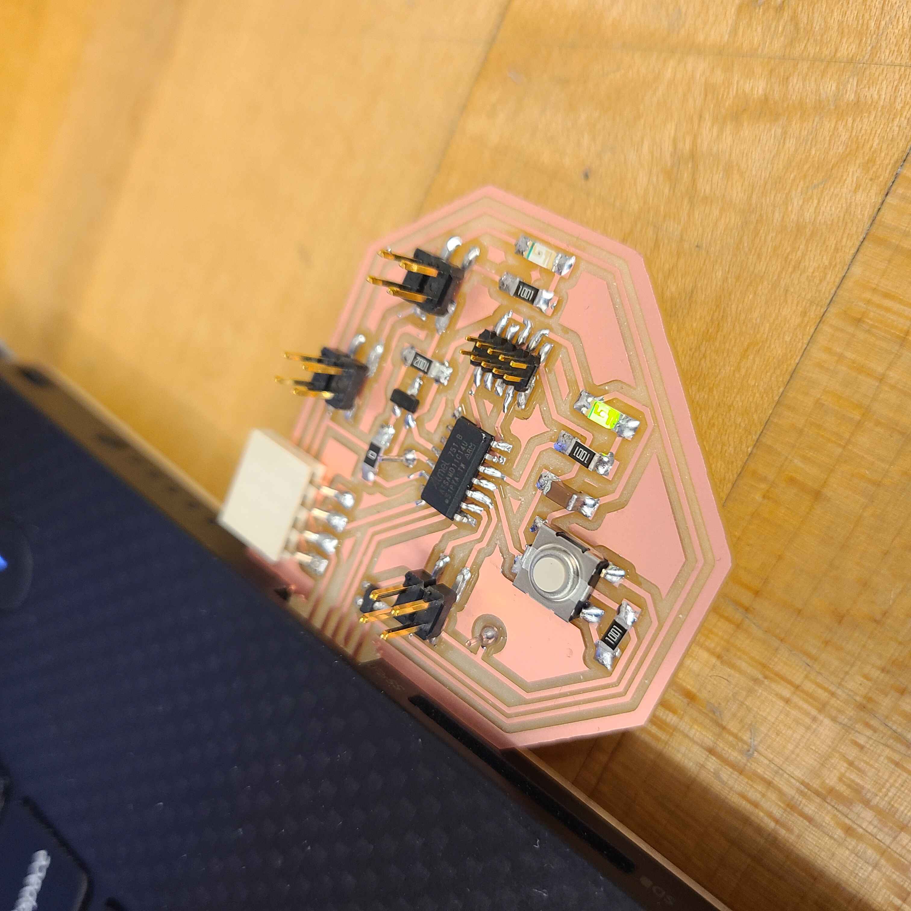
So here's the PCB talking to my laptop and making my green control LED light up. At this stage I thought everything was going swell so I copied some code off of a youtube tutorial (Pressure Sensor - Arduino by Ovens Garage) and hit send.
Not only did my SAMD11C refuse to eat the code due to insufficient flash storage but it also suddenly stopped working. I thought for a moment that my pressure sensor killed my microcontroller due to a quirk of the sensor I didn't forsee.
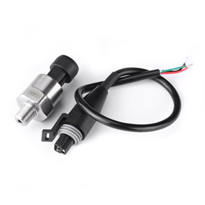
Time for a quick digression. This 100psi pressure sensor sends out a voltage signal of 0.5V when the pressure is 0psi and a value of 4.5V when the pressure is 100psi. Since my D11C operates on 3.3V, a 4.5V signal onto its pin would fry it. I, however, didn't think of regulting the voltage with something like a voltage divider with a 1k ohm resistor to the transducer's signal pin and a 2k ohm resistor to gnd which would have reduce my voltage from 4.5V to 3V.
But since my code didn't load due to insufficient flash stroage it meant my D11C couldn't have gotten fried. I went and rebootloaded my microcontroller while erasing the orignal bootload and lo and behold the D11C was back alive.
After this I spoke to Anthony a bit and he figured out that if I changed my pressure value variable from a float to an int my code would be significantly skinnier. I compiled the code in front of him and to my surprise this small change got me comfortably within the flash memory limit. Time to connect the transducer, send the code and see what happens...
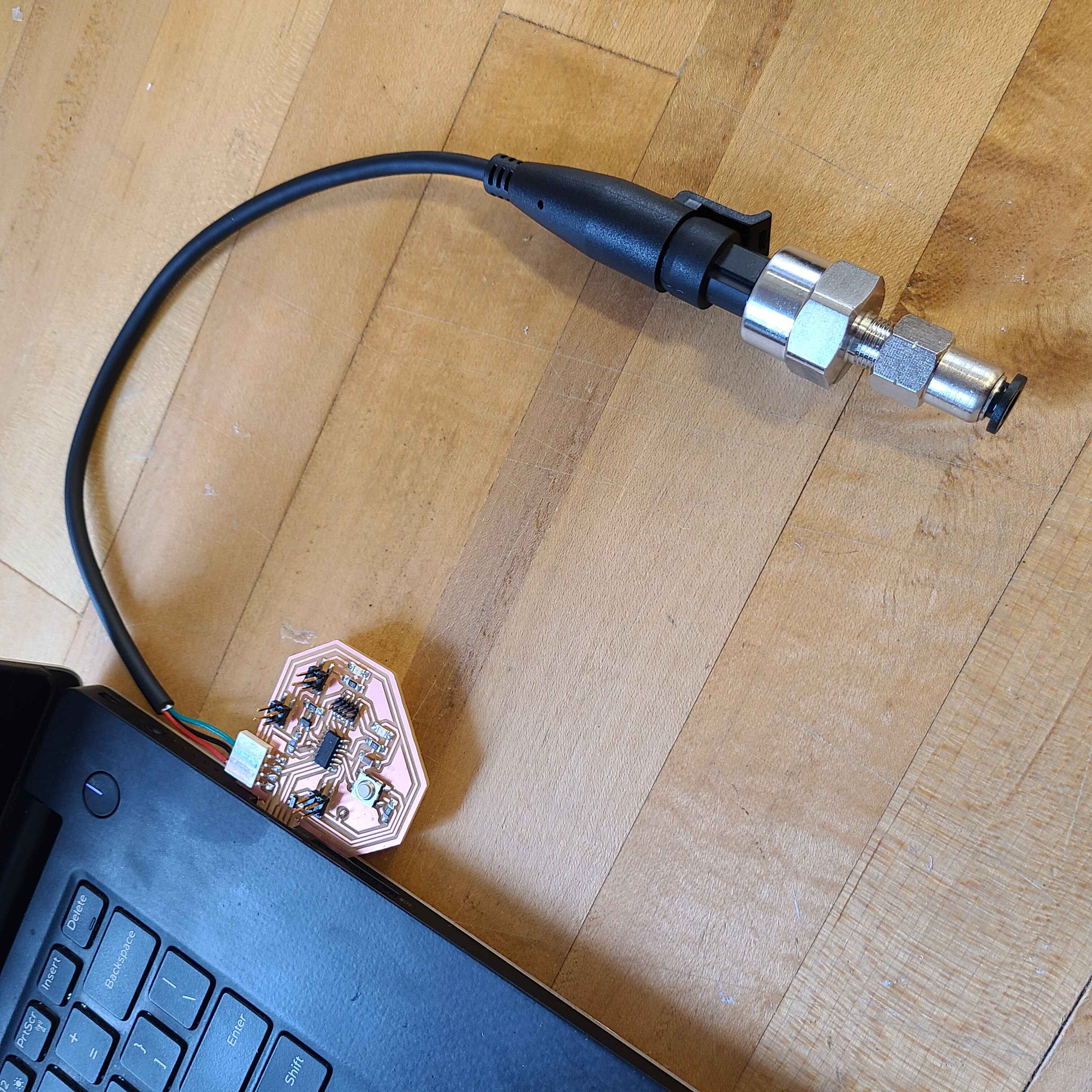
YES! It works! The transducer is sending a steady stream of pressure readings to the Arduino IDE serial monitor. I even give it a bit of a blow to test my lung but only get an uptick of 2psi... weak...
I see I need to do some adjustments to get the transducer to read 0psi when at rest but so far this is a good start!
Below is the code for the transducer.
	const int pressureInput = 4;
	const int pressureZero = 102.4; // analog reading of pressure at 0 psi
	const int pressureMax = 921.6; // analog reading of pressure at 100ps
	const int pressuretransducermaxPSI = 100; // psi value of transducer being used
	const int sensorreadDelay = 250; // so I can read
	const int baudRate = 9600;

	int pressureValue = 0; // variable to store pressure reading


	void setup() {
		 SerialUSB.begin(baudRate);
	}

	void loop() {
		pressureValue = analogRead(pressureInput);
		pressureValue = ((pressureValue-pressureZero)*pressuretransducermaxPSI)/(pressureMax-pressureZero);
		Serial.print(pressureValue);
		Serial.println("psi");
		delay(sensorreadDelay);
	}