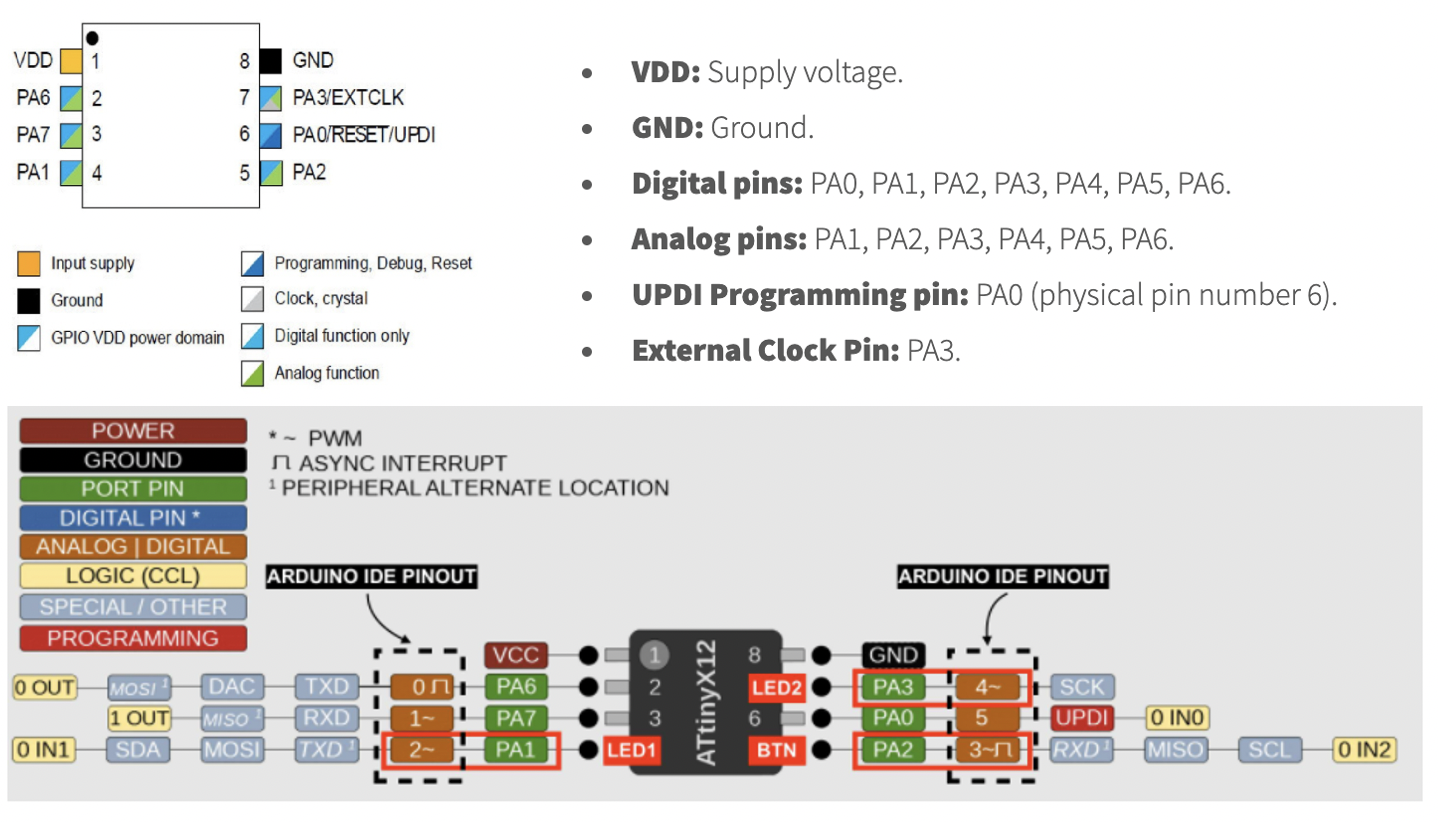
2. To read the datasheet for AVR ATtiny412 and correlate their pinouts with Arduino Uno.
3. I also plan to learn TinkerCAD to simulate my circuit at a high level for now.


(b) However, Jake told me I do not need "pyupdi" to flash/bootload my ATtiny142 board and I can directly run the program using Arduino IDE by settiing up the parameters in Arduino tools. So, I followed his advise and executed my sketches (Arduino compiled codes).
(c)Solving Confusion about Correlation between ATTiny412 Microcontroller & Arduino IDE Pinouts: I was confused about the Pin-Outs given in the datasheet for microcontroler as they were not properly representing Arduino's pinouts. But, next day, I was able to understand the whole concept of pinouts from Fab Lab's and Fab Academy's previous year's weekly assignments. For instance, I would like to mention the assignments on ATtiny412 led by Nadieh Bremer.
Finally, I understood from the schematic below that the microcontroller pins 7, 6, and 5 corresponds to the Arduino pins 4, 5, and 3, respectively, and so on.

(d) I pasted my own code after simulating it in TinkerCAD, compiled it in Arduino, saved it, and then uplodeded that in my board to blink it.

(e) Thanks to Manu as well for her help. She has been very helpful to me as well as to everyone throught the course. She also helped me today in characterizing and briefing me the few fundamentals of electronics.
(f) Delaying the signal pulse length: I was able to simulate in online to light up (high/1) the LED for 1 sec after each 3 seconds of break (low/0). The source code is as follows:

But when I tried it on my board, the opposite happened, i.e., lighting for 3 sec after each 1 sec of break. But, I didn’t know how to fix it. The reason could be the fact that my LED is connected between resistor and VCC in my PCB board while in TinkerCad the LED is connected between resistor and Ground. But, I am not sure. I will need to talk to the TAs to confirm/rectify my theory.
Interestingly, if I inverse the delayed option (i.e., break time) between the subsequent commands in the loop structure, I can get what I want, i.e., LED lighting for 1 second followed by a 3 second break before it starts the next round of second-long pulse.
(g) Fading LED programming: By slightly editing the code from previous year's works at Fab Academy I programmed my board to produce a fading LED.
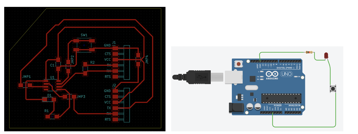
(h) Push button to control the LED: First, I did the simulation to design the circuit first, which worked out pretty well using the push button. Unfortunately, it is not possible in my PCB because pushing my button will only make connection between PA3 and ground. Because, I do not have any LED-resistor configuration in between this flow path for lighting up the LED. My code/sketch and equivalent PCB board for Pin 3 in ATtiny412 with button can be seen below. As seen two sides of my button is connected to grounds of the microcontroller and FTDI, respectively. But the third point of the button is connected to Arduino equivalent PIN 4 (which is PA3 or pin 7 of my physical microcontroller). The fourth point of the button has no connected side. Let’s see how can I work with this.

Surprisingly, I found out that I can program our microcontroller and can use the push button as an input to light up the LED in the output. Yay !!! Similarly, by slightly editing the code from previous year's works at Fab Academy I programmed my push button to control the LED. Again, I had to reverse few commands like I did for delaying the pulse length.