output devices.
Note: this work was done starting August 2022.
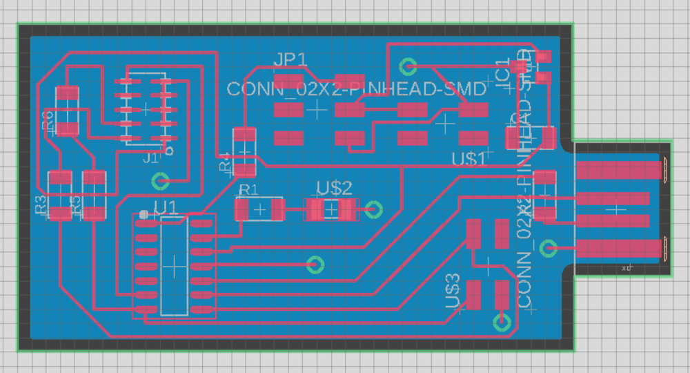
I'd now created a board that could process an input, and now I wanted to create a board with some sort of output! So that I could kill two birds with one stone, I decided to make a board that could power a servo motor, something that would be useful in my final project. Once again, this board would be connected to another one, so I included a 2x2 header on the board with the tx and rx pins routed appropriately (once again, I'll talk more about this in Week 10). Additionally, as in last week, I already had the schematic for this board from December 2021 when Zach had generously spent a lot of time helping me. However, for some reason, I had made a separate board with an LED on it, which Anthony suggested I just put on my servo board. (I wanted an LED on my board for testing as well as aesthetic purposes.) Therefore, with the simple inclusion of the led into my schematic, I was ready to route!

Once you get the hang of it, routing is not really hard; it's a little like a puzzle. However, it's still pretty time consuming: the microphone board and the servo board both took around 2 hours to route. I was actually quite proud of my routing skills on this board cause it looks very nice (not hapazard like my past boards) and very "rectangular." Please look at Week 8 for my routing tips!

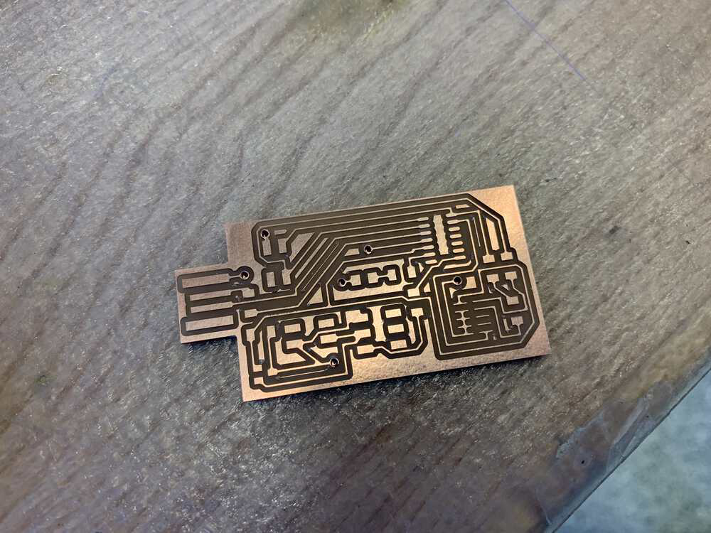
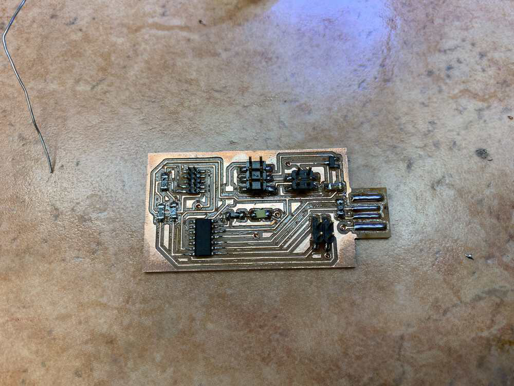
And then I was ready to mill and solder. As mentioned previously, these steps had been my bottlenecks before, but not anymore. These steps were fairly uneventful for me, other than the fact that I forgot to solder on a jumper 0 ohm resistor and was stupidly wondering why my board didn't have power. (Of course, Anthony had to point my mistake out to me. I'm so sorry Anthony!) A trick that has been helpful for me in learning more about the whole process of manufacturing a pcb is to not feel intimidated by the process, just because it looks so different. At the end of the day, a pcb is just a tiny circuit!

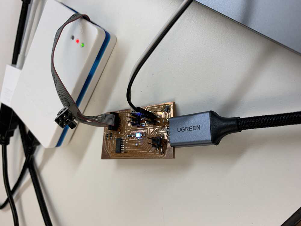
However, what was new to me about this board was that I was not powering it using USB. Instead, I placed another 2x2 header on the board which was providing the 5V necessary to power the board. Therefore, Anthony gave me a female adaptor to attach to the correct pins on my 2x2 header. Then we plugged in the male connector and plugged everything in. Unfortunately, the Atmel ICE showed that my board did not have power. Anthony then showed me how to use the multimeter to probe and see if we were getting the desired voltage throughout the connection. Turns out, the female and male headers were not making proper contact, so Anthony bent the male header so that it would. Success! My board now had power. I burned my bootloader on using edbg and Atmel ICE, and now I was ready to program.


I was so excited to get my little led blinking, that I did not think properly and made a mistake. It was late, Anthony had left, and I was programming. Everything seemed to be going okay: the program was being sent to the pcb just fine with no errors. However, the led would not light up for the life of me! (even when I sent it very simple code that had no chance of being wrong) Therefore, I thought my led was defective. In order to test this hypothesis, I used a power source and connected the ground and power in one orientation to the LED. When the LED still did not light up, I connected it in the opposite orientation. This time the LED did light up! I then remembered that LEDs are polarized and can only be soldered on in one direction. Therefore, I went back and re-soldered the LED on in the correct direction. However, when I came back, my board was all of a sudden not being recognized by my computer, and moreover, by board had no power. I was extremely confused. All I had changed was the LED? I even made sure to check I hadn't actually introduced solder bridges while fixing my LED. After trying for a while to figure it out, I gave up and left.
The following day, I showed Anthony my board and explained the situation. He then explained to me that the way I tested my LED was bad. When I had the ground and power flipped and the LED was not on, I was forcing current to go in the wrong direction. This is apparently very bad and the damage can literally be anything. In my case, seems like I had shorted my microcontroller and the regulator, which is why my board was not working. After replacing those parts, my board started working again! I wrote some quick code to get my LED to flash. Now time to get the servo motor to work.

Before getting the servo to work, I first had to understand how the servo worked. I got a quick crash course from Anthony about servos:
- Most servos have a standard 3-pin plug: power, signal, and ground. Unfortunately, the color scheme of the wires is not always the same, but the good news is that the inputs are always in the same order. (Additionally, ground always seems to be the darkest color wire, brown in my case.) Additionally, make sure to connect your servo to an analog pin on your microcontroller.
- Programming a servo is not very difficult once you understand how it operates. The total wave period for servos is 20 miliiseconds and you shoudl always adhere to that, or bad things happen. In that wave, part of the time the signal is high, and the remaining time the signal is low. When the signal is high for 1 millisecond and low for 19 milliseconds, then the motor is all the way in one direction. Similarly, When the signal is high for 2 milliseconds and low for 18 milliseconds, then the motor is all the way in the other direction. In between 1 and 2 milliseconds gives us positions in between, but be careful to always have the wave period add up to 20 milliseconds. In order to keep the motor in a certain place, you have to continue sending the desired wave over and over again (not just once).
After learning all this, I wrote a simple program to test my servo by just getting it to move back and forth. After uploading the code, the servo did move, but not as I had desired. After consulting Anthony, we came to the conclusion that the servo I had was just weird. This is because 1 millisecond and 2 millisecond did not seem to be the "extremes" of the motor movement. Instead it seemed to be 0.5 milliseconds and 2.5 milliseconds. (We discovered this by looking at the data being output from the oscilloscope.) Weird. I asked Anthony why this might be the case, and he explained that while 1 and 2 milliseconds is the correct theory, sometimes manufacturers are annoying and don't follow those standards (and also don't document the changes they made!) Anyways, with these changes, I got my servo working!
ffmpeg -i servo.mp4 -c:v libx265 -vtag hvc1 -c:a copy servoCompressed.mp4
Finally, here are the working files: Schematic PCB Arduino Blink Code Arduino Servo Code