
Rima Makes (almost) Anything!
Fall 2021

Fall 2021








Rima Das is a second year graduate student in the Mechanical Engineering department at MIT studying design theory and methodology.
She is passionate about design, engineering, education, justice, and the arts. You can reach her through her personal portfolio at rimadas.myportfolio.com

View my final slide and final video below!

My final project idea is to make a Chladni Plate side table. Chladni plates are typically made of metal and covered with sand. When the plate is vibrated, the sand moves into really interesting patterns that reflect the nodes of the waves. I am particularly fascinated by this phenomena since it is a very interesting and visually appealing visualization of a scientific concept. I’m a big fan of science and art concepts that are naturally linked, and I think that will end up being a common theme for some of my mini-projects along the way.
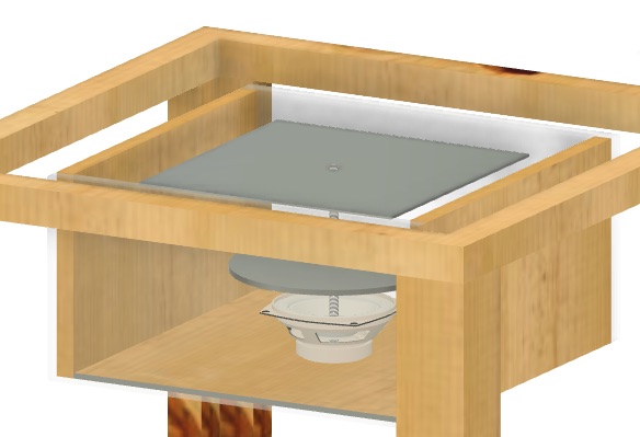
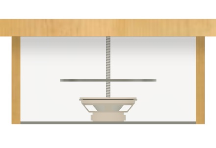
Normal Chladni plate setups are messy and noisy and not quite practical to have running constantly in an apartment setting. The vibrations needed to produce the patterns aren’t the most pleasant to listen to and the sand can spill everywhere. My goal is to create a way of enjoying these beautiful patterns without listening to the sound and without scattering sand! Thus, I propose mounting a Chladni plate setup inside a side table. The actual noisy parts will be housed in a sound dampening case. The table will have a clear removable top so that the plate is viewable just below. The removable top will allow me to scoop up the sand and put it back on top of the plate as needed.
I started by making a rough sketch of the setup on my iPad to get a sense of how I wanted things to look overall.

Next, I used Fusion360 to CAD my proposed design and used appearances to try and get it to look as close as possible to the idea in my head. I modeled everything myself except the speaker since I plan to buy a readymade speaker. I left the soundproof box clear in the model so that it would be easy to see the internal components for my documentation. My goal is to use some of the weekly assignments to work on pieces/prototypes of this (eg. make the table for the “Make something big” week). I used parametric modeling for the first time and am already a big fan- it feels like a gift to my future self! I’m sure I’ll have to make many changes along the way but I am looking forward to seeing how this turns out!


This week, before beginning electronics, I wanted to chat with Anthony about my final project. In particular, I was interested in figuring out how I can start using each week to build towards my final project. Anthony mentioned that the electronics week items would be relatively generic and could potentially be used towards the final project anyway. Since my electronics knowledge is fairly limited, I decided to go for the standard assignment this week but had a great conversation with Anthony about my project and some of the logistics and constraints. I am including those insights below!
• I will likely need to buy my own speaker, though it is possible that I could borrow a smaller sized one from EDL.
• I will need to get a wall wart to plug this into the wall: I can probably get that from Anthony.
• The input waveforms should come from the SAMD on a board I create. They can be computed on the fly or done through a lookup table with pros and cons to both approaches.
• The audio input will also come from the SAMD using a digital to analog converter.
• For my audio amplifier, I can use LM4871. Anthony recommended looking at a reference design as a starting point.
• As a general piece of advice, Anthony recommended drawing out functional blocks and identifying the crucial features, nice-to-haves, and stretch goals for the project to help make last minute decisions easier.
• One potential stretch goal is to implement bluetooth to be able to control frequencies from my phone or add a screen to the table.
• Feasible goals include adding a knob or button to cycle through different frequencies.
I decided to use Make Something Big week to make progress towards the table design of my final project (For more details, please check out my Week 6 page). There are a few key features of this design that I want to highlight:
1. A table top with a hole in the middle that can be covered with a clear sheet of glass or acrylic. This ensures that the plate can be seen through the top while having a surface to rest things on top.
2. A platform in the middle of the table between the ground and table top to hold the Chladni plate setup.

3. Holes in the legs that mimic the vibe of Chladni patterns when you look at the table from the top.
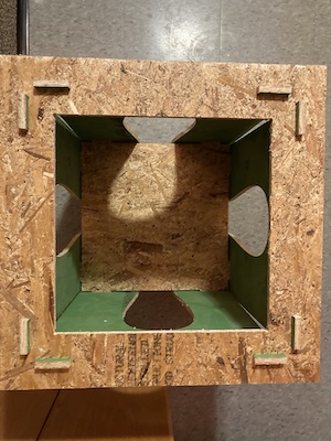
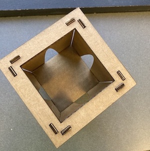
I did run into an issue with the slots in the top piece being misaligned with the rest of the setup. They should be attached to form an “L” so that the legs run straight down instead of being at a slight angle. This would ensure that it fits properly with the other tabs on the middle shelf and with the new tabs between the legs at the bottom. When I cut my final table out of nicer plywood, I will need to change that. I should be able to test it out in cardboard easily first to make sure everything fits together well. I also need to cut out a piece of acrylic to inset it in the top and sanity check the setup with the tabs on top to make sure that works well for the design. I will also need to figure out how I want to soundproof the setup- this likely means that the sides cannot be as open as they are right now with the curvy holes in the legs.
This week I worked on my input device, which will be used towards the final project. I made the step response input device using copper tape. I will be using that to create my own rotation switch to turn on and off my Chladni plate for the final project. See more details about my input device in the Week 9 tab!
This week I worked on my output device of a speaker, which is a smaller version of the one I’ll be using for my final project. I was able to use the amplifier to play different tones using the speaker. For the final project, I will use the same board to play different tones on a larger speaker which will provide the vibrations that create patterns on my Chladni plate. See more details about my output device in the Week 10 tab!
I am working on a checklist of tasks for my final project as I am hoping to start ordering and sourcing materials as soon as I can.
•Bigger Speaker (sourcing from EDS)
•Metal Rods
•Sheet Metal
•Soundproofing
•3D Print Switch for Copper Pads
•Spray Paint for Metal Plate
•Acrylic Stabilizing Layer
•Acrylic for Top
I’m also going to take a first pass at answering the questions I need to answer for the final project.
•What does it do? My final project is a Chladni Plate side table. Chladni plates are typically made of metal and covered with sand. When the plate is vibrated, the sand moves into really interesting patterns that reflect the nodes of the waves. This device is embedded inside a side table that I made and has an acrylic top so that it can be used while the plate with sand below it remains messy! There is also a “sand ramp” at the bottom that collects the sand in a groove on each side. One section of each side can then be lowered down to dispense the collected sand into a container to reuse it.
•Who's done what beforehand? People have made Chladni plates before, but I have not seen one that is embedded inside a table. I have seen a switch similar to the one I made before as well but haven’t seen it used for this application.
•What did you design? I designed the table itself, the electronics, the sand ramp, and the switch to choose frequencies.
•What materials and components were used? Full material table with costs and sourcing information is below!
•Where did they come from? See table below.
•How much did they cost? See table below. I used the fab inventory, prices from Home Depot, and prices from Amazon as appropriate.
•What parts and systems were made? The physical table, the electronics, and the entire Chladni plate setup. See details in the table below!
•What processes were used? CNC machining for the table and PCBs, laser cutting, vinyl cutting, 3D printing. More details can be seen in the table below!
•What questions were answered? I was starting from scratch with very little experience in most of the fabrication methods I ended up using for this project! It was very exciting to make a Chladni plate from scratch. In particular, being able to use a microcontroller to control tones rather than a frequency generator made this project much cheaper than examples online. I had a ton of questions around electronics that were answered through the course of this project, especially in the last few weeks. Using the earlier weeks to work on bits of my final project was incredibly helpful for scope and making this feasible for me.
•What worked? What didn't? The basic functions of the setup all work great and there are several ways to extend it further. I am able to control the Chladni plate with a switch and get it to disperse salt to display a pattern for a given frequency. I am also able to collect much of the salt for reuse. I am able to dampen some of the sound, but not all of it. In terms of things that didn’t work, I ran into a bunch of issues with electronics- I am so thankful that I made my initial board several weeks ago and had time to debug over that period of time. I was so frustrated to have to remill my board again this week but it honestly looks a lot cleaner and I’m really happy with it. I also ran into some issues with trying to figure out the best way to attach wire to the metal pin on my switch- I used a heat gun with heat shrink for a bit and it melted some of my 3D print and made the hole wider, so my perfect press fit was wobbly- so disappointing at the time, but after a few deep breaths I was able to glue it in just fine. If I were to continue the project, I would like to be able to switch between different frequencies so that it can display multiple patterns without me having to load in new code. I would also like to contain the salt more such that less of it gets through the holes in the side of the table. I would also like to dampen the noise further, since the sound is still pretty annoying and amplified because of the nature of the device.
•How was it evaluated? The critical portions of my project were being able to get the Chladni plate working and displaying different salt patterns, being able to embed it within the side table, controlling it with a switch I made myself, and being able to collect at least some of the salt that shook off.
•What are the implications? Since I was able to achieve all of the critical pieces of the project, I consider this a success! I definitely took Neil’s advice to finish something rather than not finish many things and spent a lot of time up front testing different subassemblies to ensure that they would work and that systems integration wouldn’t ruin me!
•Prepare a summary slide and a one minute video showing its conception, construction, and operation: Slide and video are at the top of the final project page!
•Your project should incorporate 2D and 3D design: 2D design was used for laser cutting acrylic parts, CNCing OSB, and vinyl cutting copper tape. 3D design was used for printing the rotational switch and modeling the foam core salt ramp to get accurate measurements.
•additive and subtractive fabrication processes: Additive: 3D printing, Subtractive: vinyl cutting, CNC machining, laser cutting.
•electronics design and production: I designed a custom PCB for this project and used both input (step response switch) and output (speaker) devices for the project.
•embedded microcontroller interfacing and programming: I programmed my board such that the input device would turn the output device on and off for a specific predetermined frequency that makes a nice pattern in the salt.
•system integration and packaging:I had a relatively straightforward experience with systems integration since I tested a TON and each time would combine a few more subsystems to test. I had tested my board with the input device and my board with the output device separately. I made sure my Chladni setup fit inside the table before I bolted everything together tightly. I made sure the amplifier worked fine with the large speaker and did several tests of Chladni patterns before attempting to permanently put the entire setup in the table. I tested my input device controlling a small speaker since I could do that outside of the Chladni setup and was able to troubleshoot my code that way before hooking things up to the large speaker. I also made most of my pieces modular so that if they need to be disassembled, they can be. I am really proud of the salt ramp that I made and it’s been working really well for collecting the salt and allowing me to gather much of it up again. I wanted to keep the sides open, which means that not all the salt is collected (and the sound is still fairly loud) but having the salt ramp serves a dual purpose of providing a cleaner finish and collecting the crystals. I also was able to tape most of the wires up behind the soundproofing material so that they can be accessed if needed, but aren’t occupying visual space and the overall presentation looks cleaner.
•Where possible, you should make rather than buy the parts of your project: Noted and done!
•Projects can be separate or joint, but need to show individual mastery of the skills, and be independently operable: N/A as my project is individual.
•Present your final project, weekly and group assignments, and documentation: Will be done on Monday, Dec 13!
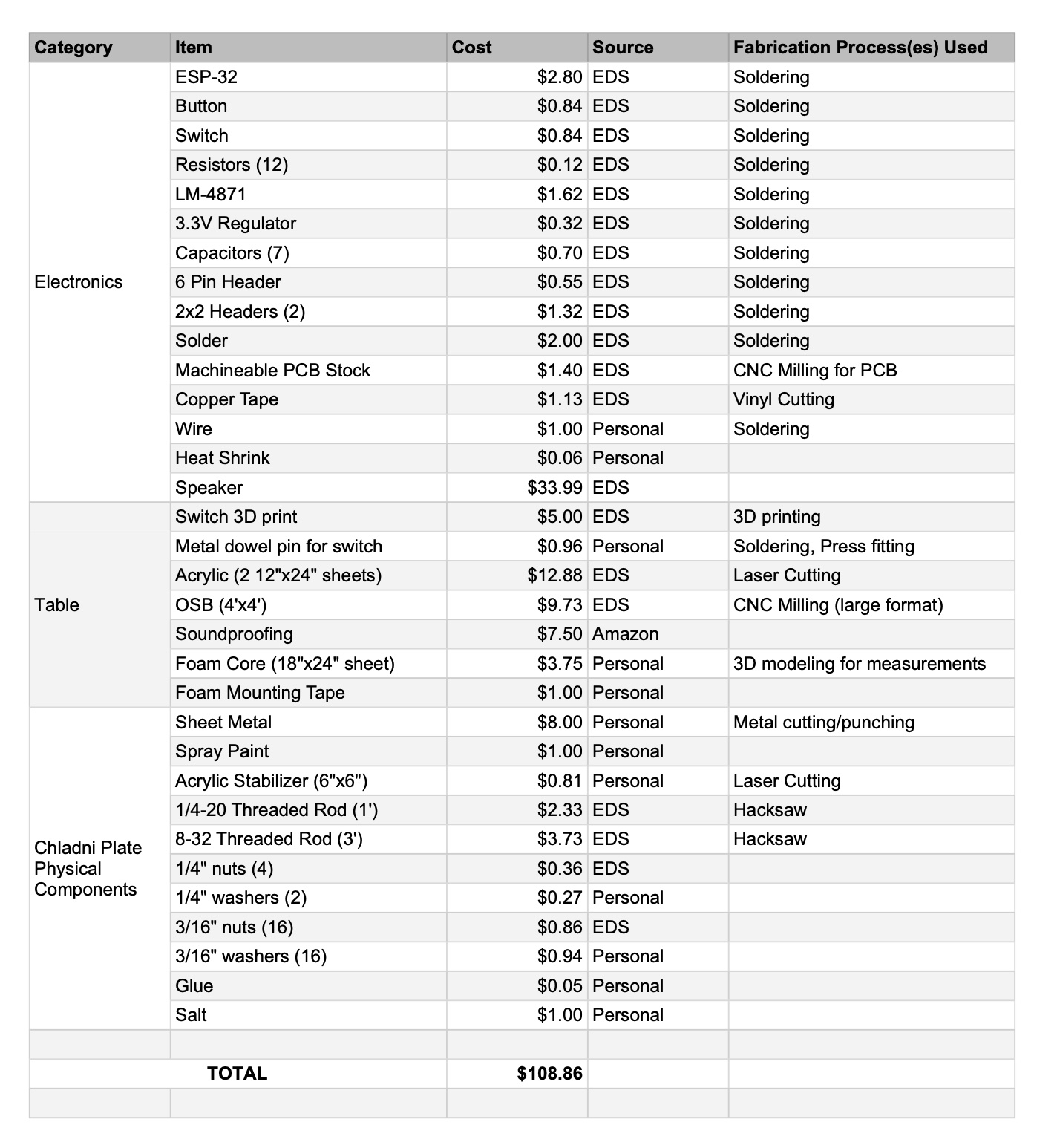
Table:
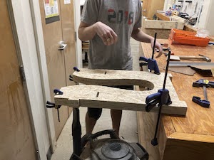
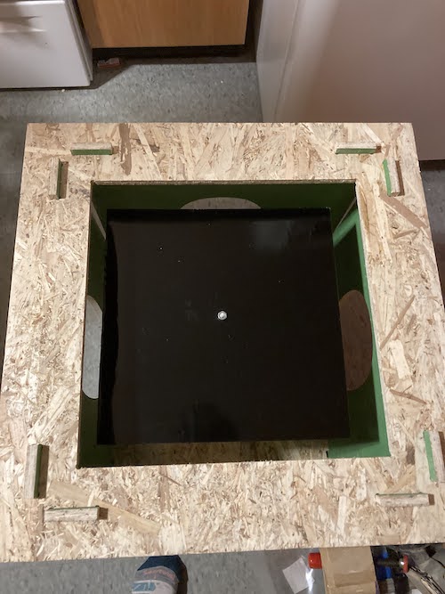
The first few days of this week have been focused on sanding, sanding, sanding! I sanded down the OSB for my table from 60 to 100 to 150 grit and now it’s super smooth, at least compared to how it was before! For now, I am not painting it, but I might paint it later to match my apartment. As a result, I am not gluing it together yet since if I decide to paint it later I’ll want to do that with the pieces taken apart.
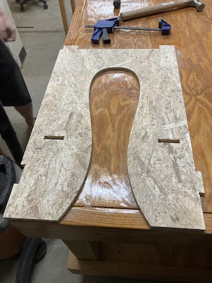 I also laser cut the top of my table. Since we only have 12”x24” acrylic sheets and I needed a 16”x16” piece, I cut it out as two triangles that slot into the top.
Physical components of the plate:
I started this week by cutting down a larger sheet of aluminum that I already had to be a square. I marked the center and used a sheet metal punch to cut a 1/4 in hole in it. Then, I spray painted it black to create a contrast between it and the salt.
Next, I measured the size of the speaker and laser cut an acrylic stabilizer to block the sound from the rest of the plate. It has holes the size of the holes in the speaker and a larger hole in the center for the main rod to go through. I then used a hacksaw to cut down some threaded rod to get it to the right length to support the stabilizer and the top plate.
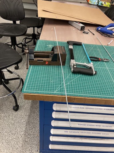
I cut 4 pieces of 8-32 threaded rod, each about 7.5” long to go through the 4 holes in the speaker and through the stabilizer.

I cut 1 piece of 1/4-20 threaded rod to 1’ long to go from the center of the speaker, through the stabilizer, and through the plate. The goal is that the sound is only traveling through this rod to the center of the plate. Through my testing, I found that it’s important for the plate to be a slightly loose at the top to get the best results (don’t tighten it down with washers, but make sure the nuts are hand-tightened so that the entire plate isn’t wobbly).
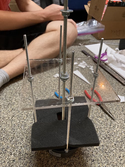
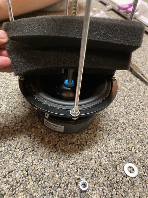
I did a bunch of testing with this setup inside a cardboard box to make sure everything was working before screwing down the threaded rods to the stabilizer with washers and gluing the center rod to the center cone of the speaker. I also cut a hole (for the middle rod) in a small piece of soundproofing and put it directly on top of the speaker in the interest of muffling some of the noise.
Rotational switch:
I started by testing the electronics with the strips of copper I used during input week. With some feedback from Anthony, I added an additional resistor to the bottom of the pins in the 2x2 header I was attaching the copper strips to. I then started with a modified version of the sample code from here to sense the distance between the two pads and I got it to read different values for different distances between the copper pads.
Next, I CADded and 3D printed a rotation switch. I tried to print it all together since the part that rotates is constrained inside the top portion of the part that stays stationary. It also has a small hole in the back for wires to come out of. All of this meant that there was a lot of support material for me to take out! Once I removed all the support, I found 2 things: 1) that my rotational part was just short enough to come out, which meant I could have printed it separately (*facepalm*) and 2) that the rotational part was so thin that it was quite wobbly inside the channel. So, I decided to print a new thicker rotational part that would fit more snugly inside the channel and provide a smoother rotation.
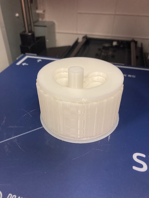
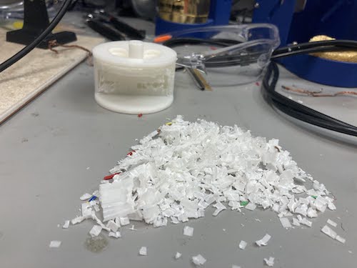
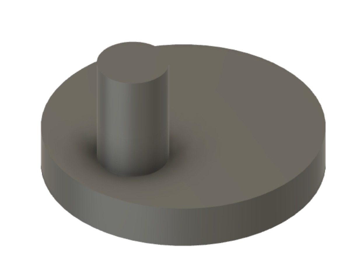
My next step was to test the setup with the copper pads inside the switch. Even though I originally had distance working well with the copper pads, it was much less reliable when I integrated it into the switch. The distance threshold seems to be pretty small, but I was getting a very reliable reading in my code when the two pieces of metal touched each other, so I decided to make the switch trigger upon contact/circuit completion instead. I drilled a hole in the bottom of the swivel portion and press fit a metal dowel pin in. I also vinyl cut a copper pad for the bottom that would cover the middle section. So if the switch was all the way to the right or left, it would be off, but if it was in the middle, it would be on. This is because I plan to mount it vertically such that gravity naturally keeps it in the off position regardless of which side it’s on. This prevents unintentionally turning it on. I soldered wires to the copper pad and wrapped wire onto the metal dowel pin. I struggled to figure out the best way to keep the wire attached to the dowel pin as I wasn’t sure if solder was the most appropriate choice. I tried to use heat shrink, but it didn’t work well and slightly melted some of my 3D print :( this wasn’t an issue for the overall structure, but it meant my perfect press fit was a bit loose, which made me very sad. However, I was able to remedy the situation by soldering the wires on and then adding a bit of superglue in the hole before press fitting the dowel pin. Finally, I combined the code for my input and output devices to test the switch with my small speaker and it worked perfectly!
Speaker/electronics:
Thankfully, I had planned ahead and troubleshooted a lot of electronics in the weeks leading up to the final (see Weeks 9-12 for more details on that). As a result, I had a working board that worked well with both my input and output devices. My first issue to tackle this week was figuring out how to power the speaker using the USB rather than an external power supply since previously I had been powering my speaker using the power supplies in EDS. Originally, I thought I could use a battery pack since the maximum voltage for my amplifier was 6V. I tried this and it didn’t work- Anthony told me that this is because the batteries can’t source much current. Instead, he suggested figuring out if I could power it directly from the USB instead. Since the board was pulling less than 1 amp from the power supply for the speaker, this was a viable option. All I needed to do was solder a wire to connect the speaker power to the USB power. This is where my nightmare began!
Normally, I enjoy soldering and don’t struggle much with it. However, I was having a very hard time soldering this wire to the right pin for the USB header. I wasn’t getting a strong joint and it was also creating bridges between the different pins. At one point, I accidentally created a short without realizing it. When I plugged in my board, Arduino no longer recognized it in the serial monitor. In the process of typing to wick away the short and remove the pins so that I could wick away the short on traces underneath them that I couldn’t access, I ripped up the traces for the 6 pin header that connects to the USB! Anthony suggested an elaborate plan of hot gluing the header back onto the board and using solder and wires to reconnect things so I could crack on with testing. I tried this but even though everything was reconnected properly, the computer still didn’t recognize my board. At this point, Anthony had also mentioned that I should eventually remill my board anyway to have a clean finish (since I had a bunch of jumper wires from previous weeks), so I decided to start fresh.
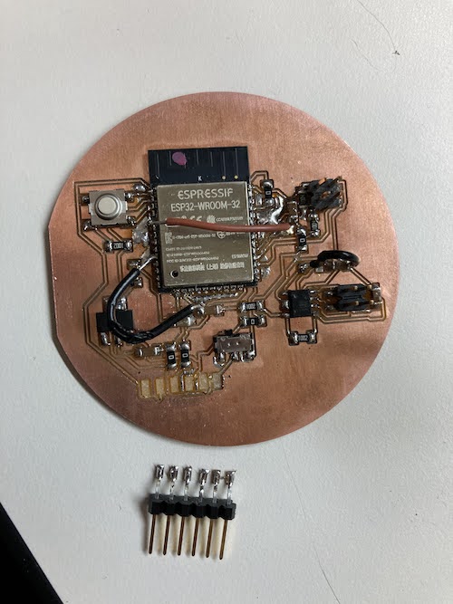
I spent a bunch of time editing my PCB layout to reflect all the changes I had made with jumper wires along the way- it’s funny to notice how what is easy with jumper wires is the opposite of what is easy to route. I thought nothing of it when using a wire to jump from one side of the ESP to the other but it was a nightmare to re-route! In order to make sense of some of my changes from before, I had to refer back to the LM4871 datasheet and I was pretty proud that I am now able to make much more sense of it. Finally, I had a new EAGLE file that I was confident in, and I was able to set up the file on the othermill on my own this time (happy that I now feel confident with both the othermill and Roland). I stuffed the board (very carefully this time) and re-tested it and the sound works perfectly off of USB! I also tested it with my large speaker and found that it worked great without any need for a heat sink, which I am excited about.
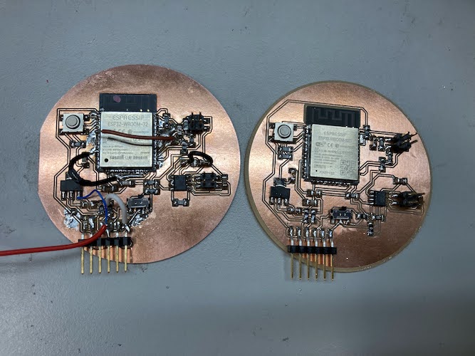
Systems Integration:
Since my project is so large and messy, I needed to do a lot of the systems integration part at home rather than in the shop. As such, I did a ton of subsystem testing early on and in the days before the weekend so that if I needed to make significant changes, I still had time to go into EDS and make them. I am lucky that I have access to a ton of materials at home and happen to live in an undergraduate dorm with a full makerspace. As a result, I didn’t have to go into the shop for things like soldering and I had access to a lot of random scraps which came in handy!
The first step to systems integration was to just put the entire Chladni plate setup inside the table and test it. The patterns were less crisp than they were when I had it inside the cardboard box, but I figured out quickly that it was because the nuts had come loose from all the vibration. This was easily remedied by adding washers and tightening them.
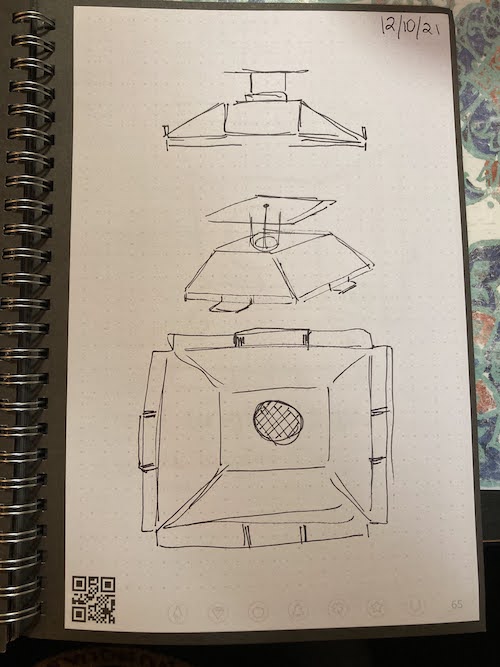
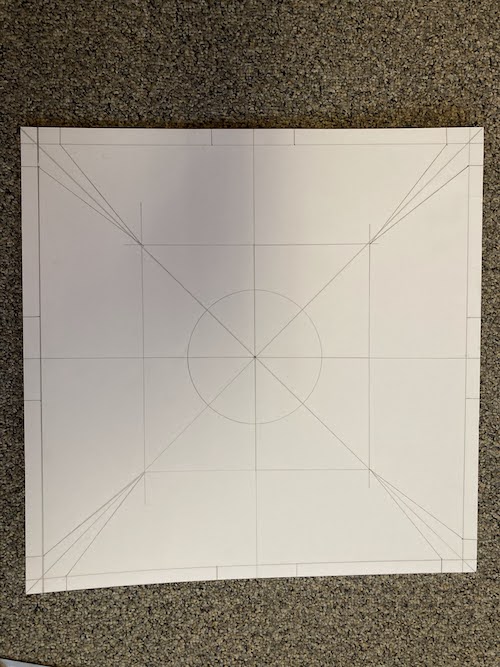
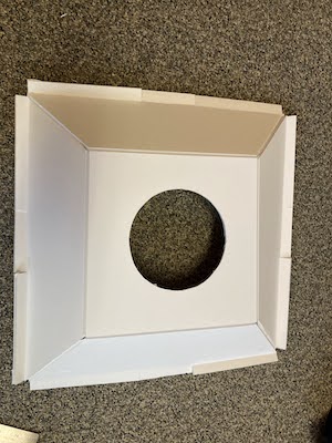
The next piece was that salt was getting EVERYWHERE. I wanted to create something that would allow the salt to collect in specific spots that I could then re-harvest. After a bit of ideation, I came up with the salt ramp- a truncated square pyramid/frustum that salt will slide down with grooves on the sides that will collect the salt. One section of the groove folds down in the middle where the hole in the table legs are so that the salt can be poured out and collected into a receptacle. I wanted to make this out of one sheet of foam core since it would provide a smooth surface and allow me to make folds and angles easily while also being a sturdy structure. Since this involved a lot of angles and math, I figured the most accurate way to get dimensions would be to CAD it and measure off of that given the dimensions that I had as hard constraints. This worked like a charm, though I could have done a better job accounting for the thickness of the foam core. This is pushing against the legs of the table, which is less than ideal but not a huge issue. I did some testing and I really love the way the salt ramp works! It definitely doesn’t catch all the salt, but it helps a ton. I’ll be bringing a drop cloth to the exhibition just to make cleanup a bit easier.
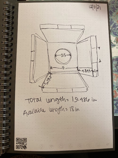
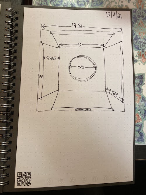
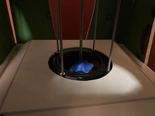
I had a lot of systems integration to do in terms of electronics management. Thankfully, I had tested the actual electronics throughout the process, so that worked well. I mounted the switch to the outside of a leg using double sided foam mounting tape. I wanted to mount the PCB on the inside but still be able to disconnect it from all the wires and take it out, so I opted to have all the wires soldered to female headers that could plug into the 2x2 male headers on my board. I made sure to apply heat shrink around those connections. For wire management, I taped everything to the side walls and had them travel down the side near the gap at the corner between the legs. For the speaker wires, I hid the extra underneath the salt ramp. Since I need to return some of the wires to EDS, I couldn’t do any kind of permanent attachment for now.
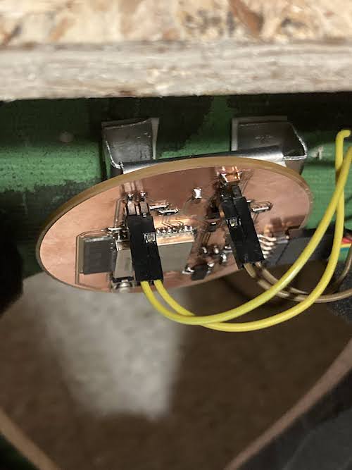
In the interest of being able to remove the PCB completely, I decided to create a hook system for it to latch in on the inside. I made a wide hook and attached it to the back of the PCB and made a slot that I attached to the inner wall of one of the legs. This works great and keeps the PCB in place even when it wiggles around a bit.
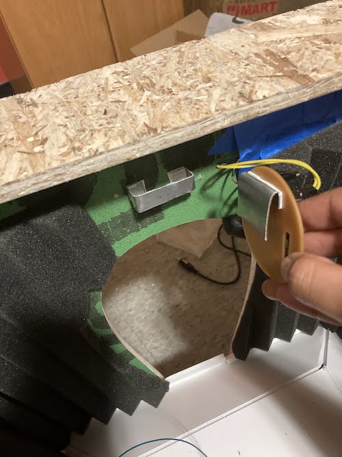
Finally, I wanted to attach more soundproofing foam to the walls of the inside. Even though these don’t soundproof the table by any means, they definitely help muffle the noise. I cut holes in them to match the holes in the table legs and used the foam mounting tape to attach them to the sides. In particular, they close the gaps in the corners, which should also help with salt management.
Finally, I put the lid of the table on and gave it a try- everything works great all put together and I am so happy with this project and proud of what I have accomplished this semester!

My final project idea is to make a Chladni Plate side table. Chladni plates are typically made of metal and covered with sand. When the plate is vibrated, the sand moves into really interesting patterns that reflect the nodes of the waves. I am particularly fascinated by this phenomena since it is a very interesting and visually appealing visualization of a scientific concept. I’m a big fan of science and art concepts that are naturally linked, and I think that will end up being a common theme for some of my mini-projects along the way.
Normal Chladni plate setups are messy and noisy and not quite practical to have running constantly in an apartment setting. The vibrations needed to produce the patterns aren’t the most pleasant to listen to and the sand can spill everywhere. My goal is to create a way of enjoying these beautiful patterns without listening to the sound and without scattering sand! Thus, I propose mounting a Chladni plate setup inside a side table. The actual noisy parts will be housed in a sound dampening case. The table will have a clear removable top so that the plate is viewable just below. The removable top will allow me to scoop up the sand and put it back on top of the plate as needed.
I started by making a rough sketch of the setup on my iPad to get a sense of how I wanted things to look overall.

Next, I used Fusion360 to CAD my proposed design and used appearances to try and get it to look as close as possible to the idea in my head. I modeled everything myself except the speaker since I plan to buy a readymade speaker. I left the soundproof box clear in the model so that it would be easy to see the internal components for my documentation. My goal is to use some of the weekly assignments to work on pieces/prototypes of this (eg. make the table for the “Make something big” week). I used parametric modeling for the first time and am already a big fan- it feels like a gift to my future self! I’m sure I’ll have to make many changes along the way but I am looking forward to seeing how this turns out!


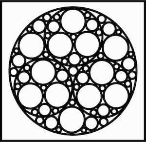
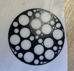
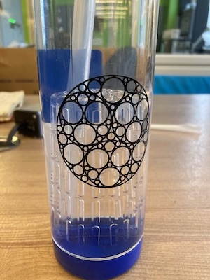
This week, I took inspiration from some of my past passions! As I’ve mentioned before, I’m super fascinated by the spaces where the arts and sciences have obvious intersections. One of those areas is fractals! I became obsessed with fractal patterns after watching Vi Hart’s videos on “Doodling in Math Class.” I took the series to heart and in high school I spent a lot of time doodling by filling in different shapes by drawing the largest possible circle inside the shape and then inside any subsequently formed empty space. For my vinyl cutting project, I decided to pay tribute to this by creating a circle doodle sticker for my waterbottle!
I had a lot of fun designing it in Illustrator and here’s the final digital image I ended up with:
I’ve had a lot of experience with vinyl cutting and I actually have a desktop vinyl cutter in my apartment that I use to make things like stickers and screens for screen printing. I was excited to try out the larger sized vinyl cutter and to use mods for the first time.
The first time I tried to cut the sticker, I didn’t clamp the vinyl down so it just made a bunch of scratches on the vinyl instead of actually cutting anything! However, it was a pretty quick cut so I was able to rerun it without any issues. It came out beautifully and I was amazed at how good even the smallest circles looked. I knew this would be a pain to weed but because I have had a lot of experience with vinyl cutting I figured I could handle it.
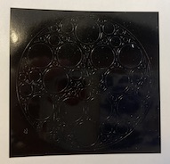
I got about halfway through pre-weeding before deciding to just go for it and stick it on and see if the transfer tape could help me pull out a bunch of the little pieces at once. Thankfully it did and so the process went a lot faster after that on the water bottle. You can see all the little pieces stuck to my hands- this vinyl is definitely strong!
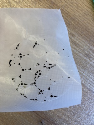
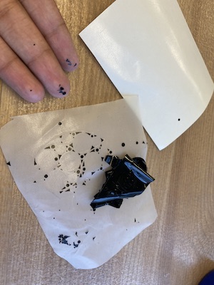
Overall, very fun process and it went really smoothly- super happy with the final outcome. Hoping to use this vinyl cutter again, maybe for some larger scale projects too now that I’m comfortable operating it!
The EECS team split into subgroups to characterize both laser cutters. I worked on characterizing the laser cutter on the right. We did several different tests to determine different properties. The first was to determine the appropriate power and speed. Anthony gave us some numbers to start with (100% power and 20% speed) and we worked from there. We worked our way down until we reached a sweet spot at 10% speed. At 12% speed the pieces could be popped out but at 10% the laser cuts all the way through.
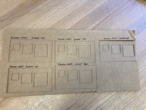
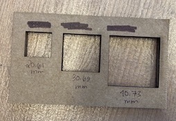
Next, we determined the kerf by cutting a bunch of squares of different known sizes and then measuring the actual square and hole size formed by the laser. We tried to engrave the sizes of the squares on the cardboard but engraving on cardboard didn’t seem to work super well. Doing the partial cut (blue line on Corel for creases) might be better. The average added length across the three different sized squares was 0.68, so the kerf would be half of that (0.34).
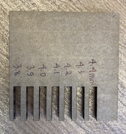
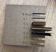
Next, we made a board with slots of different known sizes in order to see which one fit the cardboard best. We found that anything in the 4.0-4.2 range works well, depending on how tight you want the fit to be. For my project, I am planning to go with 4.0 but I will run a test first on one piece to see how that holds up since I know there might be board to board variation in the pieces as well.
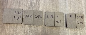
Finally, we wanted to do a test to see what settings are best for cutting through only one layer of cardboard for making a joint (the blue line on Corel). We started at the existing default, which was 5.4% power and 12% speed. After trying several different settings, we found the ideal setting to be 25% power and 10% speed.
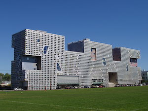
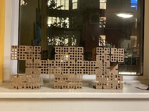
For my press fit kit, I was inspired by my undergraduate dorm, Simmons Hall, since it is known for its modular style of furniture and for almost looking like it was built of legos (photo below is from Wikipedia)! I thought it would be really fun to make a kit of materials that could be used to make a replica of that building but also make buildings in a similar style, almost like what you would get if you imagine taking apart the dorm and reassembling it in different ways.
I was inspired by the way the dungeon example pieces fit together to allow for a lot of different configuration, so I CADded up similarly square pieces with chamfered slots on all four sides. I did some with windows for the vertical walls and some without for the horizontal parts. I made the cardboard thickness, piece size, and slot width and height parametric so I could adjust after making some test pieces depending on how they turned out.

I had some initial problems with navigating the Fusion360 to Corel workflow- the dimensions were scaled incorrectly, some features of the pieces were missing, and some construction lines were showing up as part of the drawing. Anthony showed me how to turn each of my pieces into a sketch in Fusion and then save that as an individual DXF, which solved all of the issues.
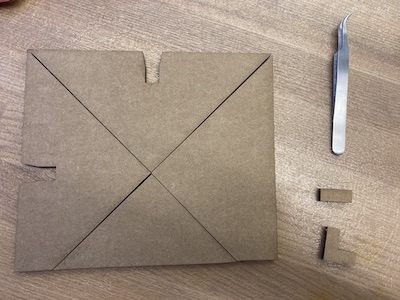
I then ran some test pieces to make sure I was happy with the sizing and I caught a few mistakes with my model that I was able to fix quickly thanks to my parameterized model! I had made my connector pieces the length of one slot instead of 2x the slot length so that they would be long enough to connect both pieces. I also adjusted the slot size using the calculated kerf to ensure I would get a good fit. Finally, I was ready to cut out a ton of pieces!
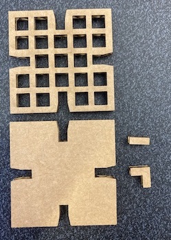
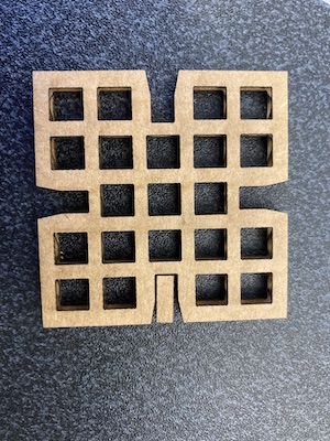
I cut out one full sheet of square pieces and one of connector pieces since each square has up to 4 connector pieces attached to it. Even though I taped down the cardboard to try and minimize the effect of the bend, there were quite a few spots where the laser didn’t cut all the way through so I had to finish some of those up with an exacto knife. Some of the window squares didn't cut through all the way either, but I'm considering that a feature rather than a bug since some of the Simmons windows are actually filled in for structural reasons as well!
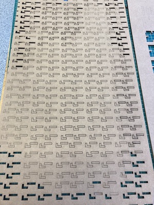
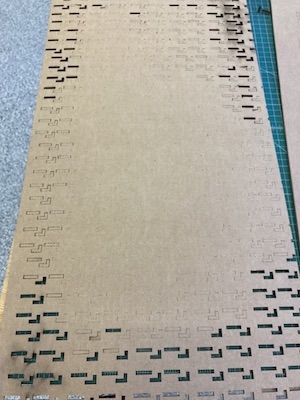
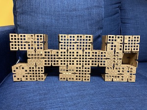
Assembly went well- the individual pieces stuck together really nicely and the press fit was perfect but the cardboard isn’t super strong for holding up multiple layers at a time (eg. when I have 3 squares on top of each other), which made assembly initially challenging because things would fall apart once I lifted them up to their vertical standing position. It would be fine for smaller structures, but since I wanted to build a model to keep, I decided to reinforce some of the joints with super glue for ease of assembly and display.
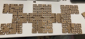

I’m super happy with the final product and have it on display on my windowsill!

This week, I started by getting trained on how to use the Othermill, the Roland, and how to solder surface mount pieces onto PCBs.
I liked the workflow on the Othermill: png to mods to gerber to device. However, when we tried to do this for the group assignment, the traces didn’t show up on the program! We’re still puzzled about why that happened but maybe the other group will have better luck. Instead, we moved over to the Roland to characterize the design rules and practice the workflow.
Things went smoothly for the group assignment and our printed board using the 1/64” bit looks very similar to the image on the HTMAA website for the 1/64” bit. The thin traces on the left on our print turned out better but are starting to peel up so I would definitely avoid making designs that use lines that thin. Everything near the 0.010 mark looked good for exterior traces and everything near the 0.02 mark looked great for both the interior and exterior traces.
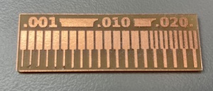
I chose to make the hello.D11C.serial.5V.1 board as it was recommended by all the course staff as a good place to start and I had no prior PCB experience. I used the Roland again, which has been having some problems with the door switch not always registering and as a result not being able to communicate with the program. This proved to be an issue for milling my board because after doing the interior and swapping out the tool it would not connect back to the computer for the final cutting pass. After turning the machine on and off several times, closing out of mods, and closing out of the mods server, the connection was finally restored and I was able to finish milling my PCB. The tool was in great shape so the lines came out very clean and I didn’t have to do any finishing with the putty knife.

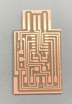
Next, I removed the copper layer near the top of the USB part so that it wouldn’t short circuit. To do this, I used the soldering iron to heat up the glue under the layer and then I was able to peel it away in a few parts.
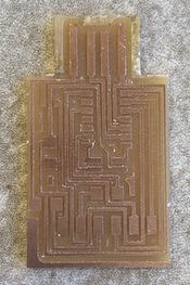
I have soldering experience, so the soldering part wasn’t terribly difficult or time consuming for me. The pro-tip of placing solder down to anchor a part was great since using the tweezers was very necessary for placing parts initially. After that, things went smoothly and soon I had a finished board!

I added a few layers of solder to the four lines that will go to the USB in order to get them to a height that will register in a USB reader. I also added a bit of vinyl on the bottom to add thickness to the whole setup. The board is now ready to test!
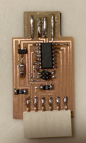
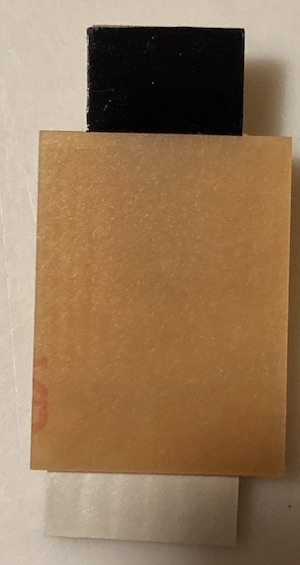
Testing was a lot more complicated than I initially anticipated and we ran into a bunch of issues with my board. First, the board design had been changed since I milled my PCB to account for a missing part, so my board was different from everyone else’s. To address that, I soldered wires to the 2x2 connector in the board so that it could be set up to program over USB.
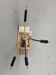
Next, we discovered that I had a 5V voltage regulator instead of a 3.3V one because someone had put parts in the wrong drawer! So, I got to work unsoldering and resoldering a new voltage regulator to my board. In the process, some of the copper traces came off, so I had to redo it a second time using the hot air to melt everything and push the part back so I could solder it in a better spot. I then used magnet wire to create a bridge in the spot where the voltage regulator couldn’t reach the copper traces. Anthony was a huge help in every step of troubleshooting- thanks Anthony!
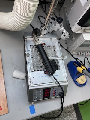
Finally, we were able to test the board and it worked! It looks a lot less nice than before but is now programmable over USB. Looking forward to doing some aesthetic modifications to the next one I try as well!

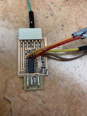

This week, our overall goals were to design and 3D print something that couldn’t be made subtractively and to 3D scan something.
The EECS section has decided to create an overall website to help document our group assignments and avoid unnecessary file storage from uploading the same pictures a bunch of times individually. You can check the page for this week’s group assignment here!
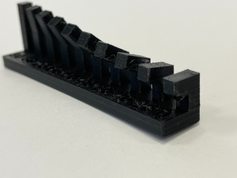
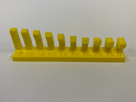
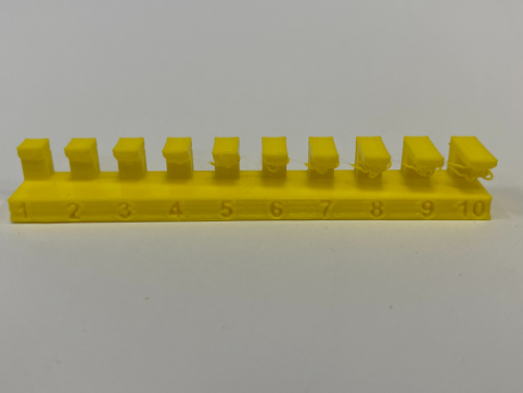
This week, our group assignment was to test the design rules for the 3D printers. The EECS lab has (at the moment) 2 Sindoh printers and 1 Prusa printer. In the pictures shown, the yellow parts are made on the Sindoh and the black parts are made on the Prusa. Generally, I was very impressed with the print quality.
A few things I learned/noticed:
1. A phenomenon called “Elephant’s Foot” can happen, where the bottom of a print squishes down under the weight of the layers on top while the layers below are still soft enough to compress. This can be seen in the photo below and can mess with dimensions- both in making the z shorter than expected and by creating a lip at the bottom. Anthony mentioned that some people circumvent this in their designs by making the bottom of a design narrower than desired so that it expands out to the intended dimension.
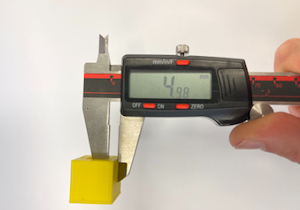
2. Both the Prusa and Sindoh softwares have a setting for turning off the top layer, which was really useful for the infill tests. We forgot to turn off the top layer for one of the prints and had to use the bandsaw to cut it off instead, which was less than ideal since that melted it a bit as it cut through!
3. I was especially impressed with the angle test- the Prusa and Sindoh both did well up to around 10 and 20 degrees, respectively which was better than I anticipated, even though that is comparable to the example images we had. I find the contrast between that and the overhang to be especially interesting, since the overhang only does well for 1 or 2 mm at most.
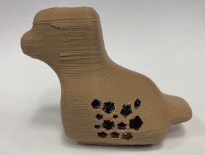
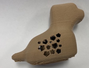
For my own design, I knew I wanted to make something inspired by a traditional Indian handicraft of making wooden carvings of a baby animal inside the mother animal. We have many of these at home that we have gotten from India, and I wanted to try making something inspired by this myself. I decided on a duck shape with an egg inside!
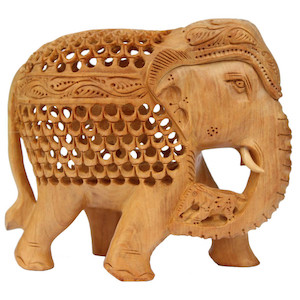
Elephant photo is from this site.
Normally, these are made subtractively by creating a lot of holes in the mother animal that the baby animal can be carved through with a small tool. However, I was designing something that could not be made subtractively so I decided to only add a few small holes in the side to allow looking through to see the inner item.
I also wanted to use this chance to explore the sculpting environment in Fusion360 to make more organic shapes. It was a ton of fun! The only thing I missed was the ability to move back in the timeline. From what I can tell, you have to do much of the sculpting at once rather than going back and changing things. It also lets you make shapes that won’t actually work once you finish the form (eg. lines twisting across each other), so it is a bit more trial and error. After experimenting with the software, I was able to sculpt a duck form I liked and added a 2mm thickness to it to make it a hollow shell.
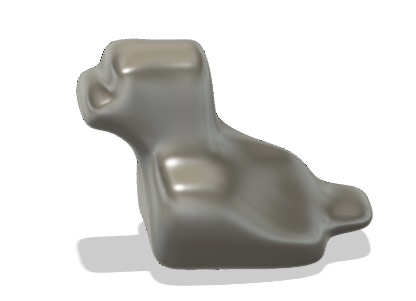
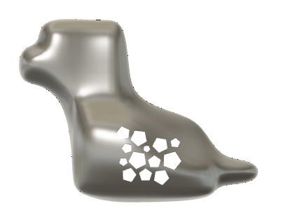
Next, I added the holes through the side. It was important to do that at this stage so that they wouldn’t go through the egg as well.
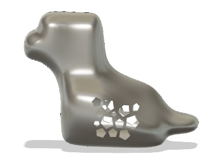
Finally, I made the egg shape inside by making half the shape and revolving it along the middle axis. I made sure that it was positioned such that it would be solidly attached to the bottom of the inside of the duck body.
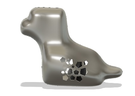
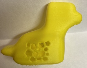
I printed it on the Sindoh, which was perfect since the filament is yellow! I had to add support under the beak since it was an overhang. I also removed the support that was automatically added inside around the egg since I knew I wouldn’t be able to remove it through my intentionally small holes in the side!

The duck printed super well and the support was easily snapped off with a pair of pliers. The holes are a bit more wobbly than ideal, so I’m wondering if that would be different if the duck was scaled up so that those pieces were larger. I also sanded the front to remove the little burrs from the support material. Overall, I’m very excited about how it turned out and am hoping to also try and print it with wood filament on the Prusa once the printers are more free after this week’s assignment.
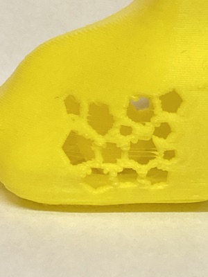


Update: I was actually able to test the duck with the wood filament on the Prusa! I used the Prusa software’s cool new feature of painting on and off supports to indicate that I wanted supports under the beak and didn’t want supports inside the cavity.
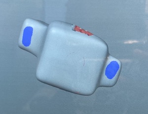
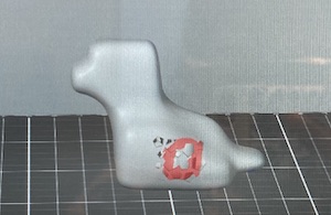
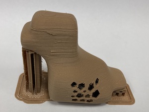
The wood filament is super interesting, it definitely has a different feel than regular PLA but it looks more like brown plastic than wood. Since it has sawdust particulates in it, it is important to have additional ventilation running when printing.
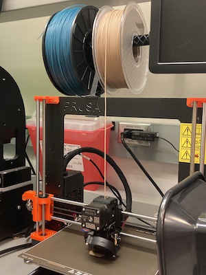
The print came out great with supports that I was able to snap off by hand. I cleaned up the holes on the side since they were still a bit stringy, but they definitely came out cleaner on the larger duck as predicted!
I had a ton of fun 3D scanning with Solomon! We decided to scan each other using the 3D Sense. It actually had a setting for scanning heads, which was very handy. It also had a setting to close the model after scanning, which turns a scan into a model that can be 3D printed.
I scanned Solomon, which went very well. I was impressed with the fact that the safety glasses scanned so well since Anthony had mentioned clear objects were especially tricky.
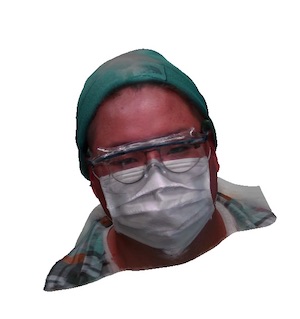
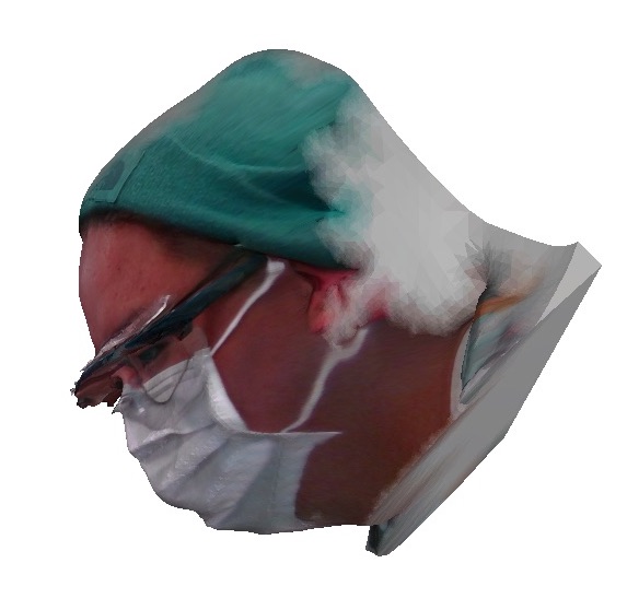
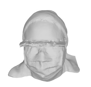
Next, he scanned me, which was a different story entirely! The scanner really didn’t want to recognize my hair, so the final scan looks kind of funky. I’m not entirely sure why this is since the background was white, but we’ll have to keep experimenting to see if there are other settings that work better. Since Solomon was wearing a hat, his model is well bounded and could probably be 3D printed successfully!
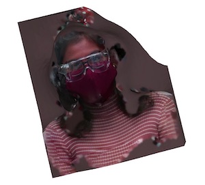
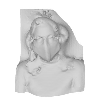
For privacy reasons, I am not going to share the 3D models of me and Solomon.

This week, I learned how to use Eagle within Fusion. It was definitely a bit of a learning curve but it’s very cool and like a puzzle to figure out how to route everything! It took me a bit to understand that I needed to connect everything in the schematic layout before it would allow me to route traces on the PCB layout. I love the feature of being able to switch between tabs easily as I definitely made changes to the diagram throughout the process. One great trick I learned from Anthony is to use a 0 Ohm resistor to give you something to route through if it’s impossible to connect traces directly. Doing the PCB layout during office hours was great. I had Anthony check over it many times and each time he caught a different error. For instance, I initially didn’t realize that the 2x5 pin had a specific layout- I assumed that since we were only using 2x2 of it that I would use the first 2x2 pins and ignore the other 6! Turns out, they each have a specific purpose and need to be wired accordingly. I also learned how the button works- only two of the 4 sides actually are connected to other things on the board. Also, the button can actually use the resistor inside the SAMD instead of needing an external pullup resistor.

I struggled a bit with the outline feature within Eagle. It’s definitely not geared towards making super crazy board shapes with lots of curved lines. I decided to try and make an outline on Procreate instead but then realized that it would be more challenging to make sure all my traces are within the outline on Procreate since the images exceed the size at which you can have multiple layers within the app. Playing around on Procreate did help me figure out that I wanted to make my board look like a lightbulb! I was able to replicate that within Eagle relatively easily and got set up to mill my PCB.
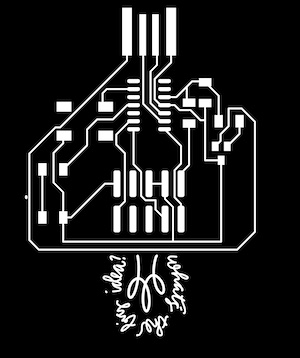
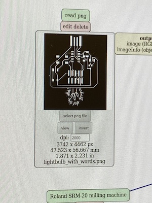
After getting everything ready to mill and starting the process, I found out that there is some kind of issue with DPI conversion between Macs and mods such that everything gets scaled up by 2! I had the correct DPI (1000) and when I started milling, it went totally off the plate. I caught it early and stopped it through the program but this board is still sadly unusable for someone else now since the program ran through a few more steps before stopping. Now I know that mac users often need to use 2000 DPI in Mods instead. The best thing to do is check the dimensions on the right hand panel of Eagle and match them to the dimensions in the first box in Mods.
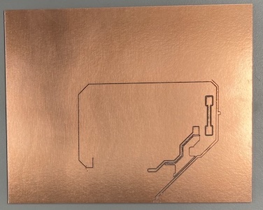
For the next iteration, I double checked the dimensions in Eagle and in Mods and flipped the board to be the other orientation for extra good measure. I definitely have a love-hate relationship with the Roland- the traces typically come out cleanly but the issue with the door is very frustrating. Almost every time I’m totally ready to go, the connection severs and I have to move the tool out of the way and start over. The last few times, I’ve fixed the issue by going back to the desktop and reopening the mods server.
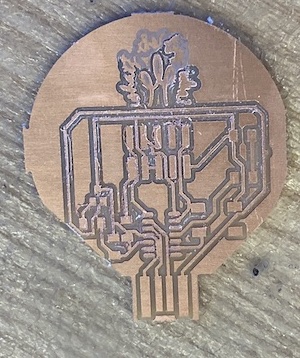
After cutting out the board (for the first time), I discovered there were quite a few issues with it. First, when Eagle exports pngs it does not include a border. As such, any straight lines in my outline that happened to line up with the edge of the footprint did not have a black/white interface line. For instance, the top of the USB was one such part. Anthony suggested taking the piece to the bandsaw, so I finished cutting it out there. Next, we discovered that the 1/64 bit I was using was on its last leg, so many of the traces were messy and some were mistakenly joined together. Not ideal! I cleaned them up with a putty knife and started cleaning up the shorts with an exacto but figured it would be best practice to put more space between them in Eagle and cut it out again so that I could fix the other issues too.
I took the images into Illustrator so that I could add a black border around them and accurately position both images. It was fairly straightforward to do that since I could make the outline layer semi-transparent to ensure that it was placed in the right spot. This way, I was also able to draw in the lightbulb wire on Illustrator rather than bringing them into procreate. I re-exported them as pngs but wasn’t sure what level of resolution I needed to export them in. I initially tried the highest level (300ppi) but that seemed to make mods rather unhappy, so I re-exported them at the screen optimized level of 72ppi.
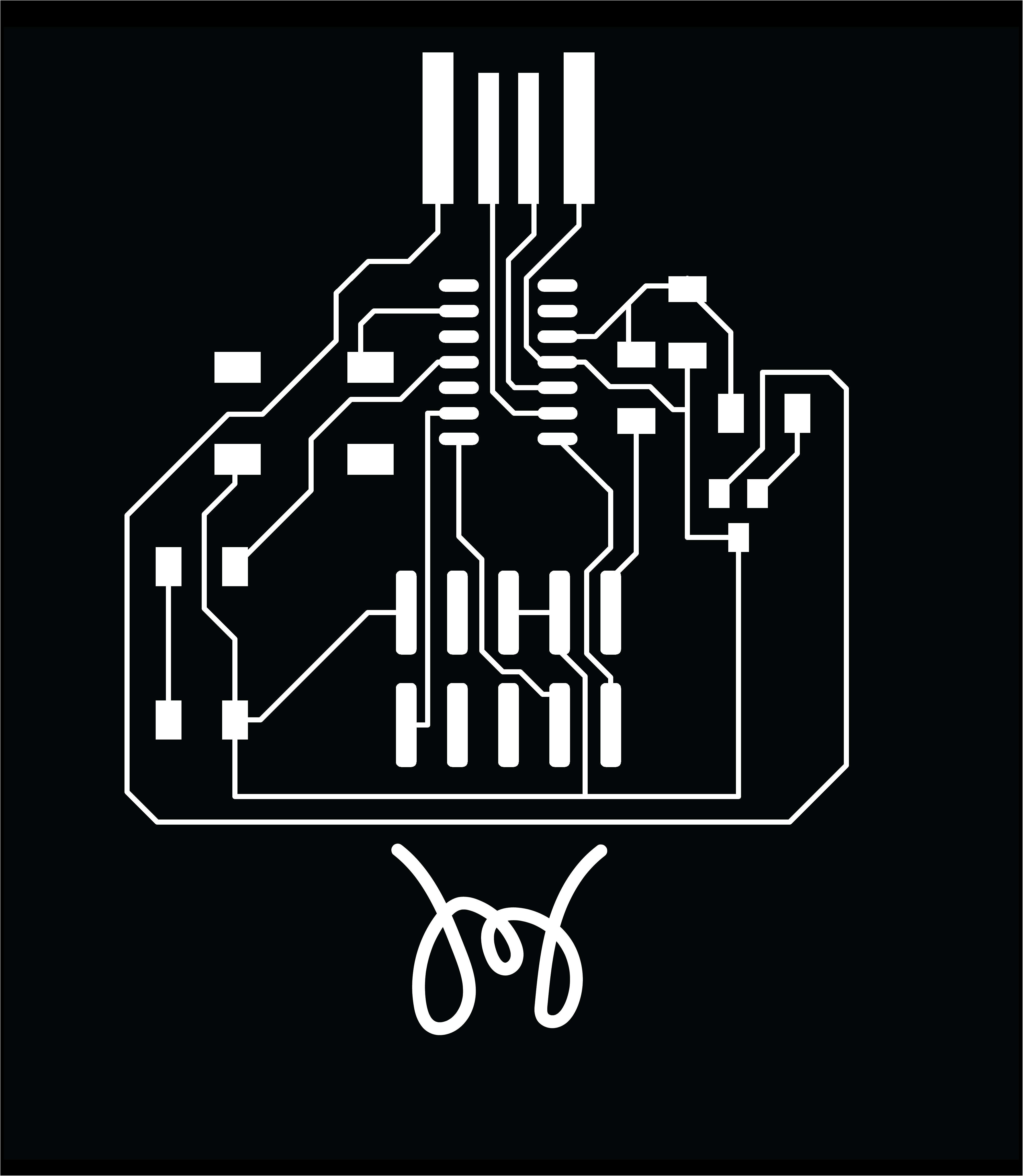

Once again, I had to change the resolution on mods to be 2000dpi to make sure the board was the right size- thanks Macs! On my next try cutting, the Roland door once again gave me a hard time. We had a new 1/64 bit so the traces came out beautifully. However, despite having a border on the image, some parts of the side still didn’t cut through. Next time I’ll have to put a bigger border on everything. Also, it put a rectangle around the entire image both in the traces and in the cuts which I didn’t expect- not sure why that happened.
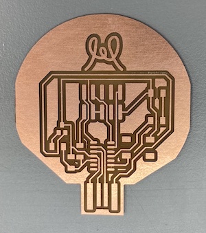
I was able to solder everything on easily- using the tweezers really helps with placing surface mount pieces! The only issue was that the 2x5 pin connector I used was a lot bigger than the one that fits our cable. Thankfully, the one I used will still work- we will just need to connect the individual wires in order to load the bootloader onto the device the first time. This is what we had to do last time as well with my PCB but I had smaller pins, so I had to solder wires to them. This time, we should be able to just use wires with female connectors that can slot into the pins I used.
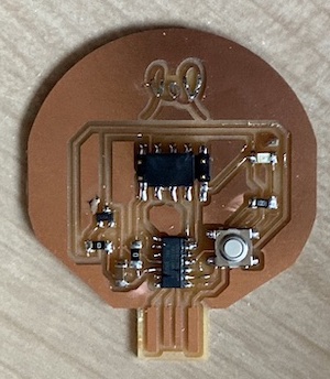
Neil mentioned in class last time that adding solder to the USB traces isn’t his preferred method since it is hard to get them to be even. Last time I had done that and also shimmed the back with a piece of vinyl. This time, I shimmed the back using five layers of vinyl to try and get to that same height. Now the board is ready to test!
Testing went nearly as well as I could have expected. Because I used the large 2x5 pin connector, I had to individually connect each pin with a wire. Thankfully, there was a relatively straightforward setup for that. With Anthony’s help, I was able to get the generic bootloader installed and headed straight to Arduino to test the sample echo code.
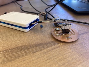
Arduino was giving me a bit of a headache until I realized that this board type isn’t automatically supported in Arduino! I followed this link to install the Arduino core for SAMD from a relatively hidden part of the course website. It took me to this link (scroll down to “Driver Installation” and follow the instructions for your OS. Finally, I was able to upload the code onto my board and get it to echo back!
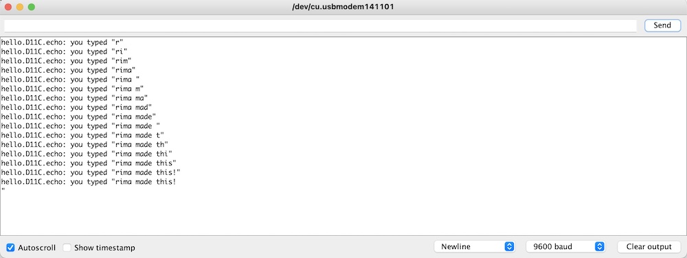
This week’s group assignment was strange because we needed to do it after finishing the individual assignment. Once I got my board working, we took it to the oscilloscope and probed around to see what was going on at different points. Solomon and I attempted to get one of the pins to modulate from high to low but didn’t have much luck initially visualizing that on the oscilloscope.

We used the image below from this link to help us figure out which Arduino pin corresponds to which pin on the SAMD. Our group page for this week will have more details here!


This week is one I have been super excited about! Since my final project involves putting a Chladni plate setup inside a side table, I decided to use this week to make progress towards the side table design. There are a few key features of this design:
1. A table top with a hole in the middle that can be covered with a clear sheet of glass or acrylic. This ensures that the plate can be seen through the top while having a surface to rest things on top.
2. A platform in the middle of the table between the ground and table top to hold the Chladni plate setup.

3. Holes in the legs that mimic the vibe of Chladni patterns when you look at the table from the top.


Eventually, the inside of the setup will be soundproofed but for now I wanted to leave it open. I created a parametric model of the table in Fusion so that I could make a mini version in cardboard before cutting the OSB. Through this process, I learned that Fusion cares about the order in which you change parameters! I had found the right parameters earlier and then scaled everything down for my cardboard model. However, when I went to change the settings back, a couple parts freaked out (left) because it updates each time you change a parameter rather than updating all at the end once you hit “ok.” This resulted in some weird features on the middle piece. I was able to fix this (right) by undoing my progress and changing the order in which I changed parameters. The other strange bug I noticed was that my spline for the interior of the legs did not scale well. For the mini model, I ended up just redrawing a simpler spline with the knowledge that I could change that feature for my final model.
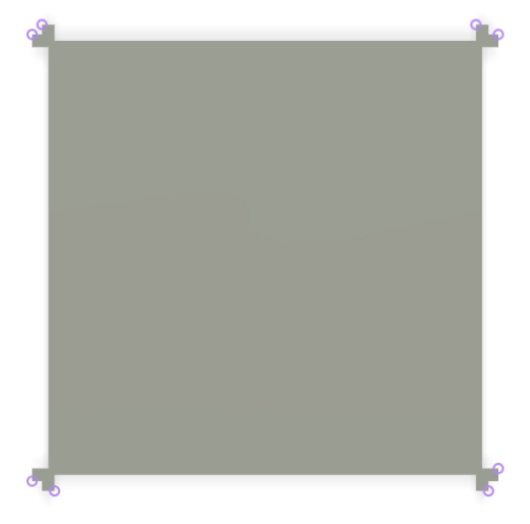

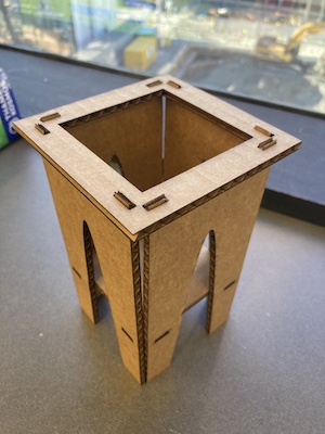
The mini model came out great and helped me a lot in visualizing how the table was going to look and fit together. It was also useful for communicating my vision to Anthony and having him sanity check my design. He recommended that I add additional tabs between the legs in the space between the ground and the bottom platform.
This week’s group assignment was to get trained on the machine in the shop and to do some testing on it. As part of our training, we cut out a test part with a tab and slots of different sizes so that we could test them to determine what slot size we wanted to use for our press fits. I liked the fit when the slot was .01 inches longer than the tab. I also measured the thickness of the OSB and found it to be 11.3 mm. I also used an awesome Fusion plug-in to “dogbone” all my slots with an 0.25 in diameter tool. Finally, with everything updated in my model, I was ready to cut!

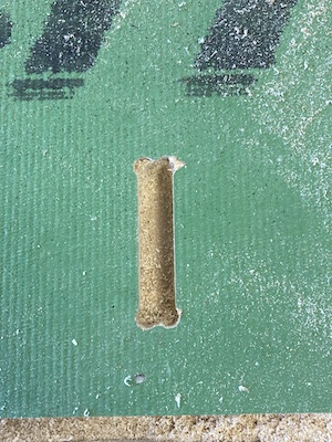
Anthony had estimated our jobs would all take between 30-40 minutes, so he scheduled hour-long slots for each of us. The whole process ended up taking a bit over two hours for us- good thing no one was signed up for the slot after mine! I learned how to set up the manufacturing settings in Fusion, but I would definitely need to practice a few times on my own to be confident I was doing it right. I learned how to zero the different axes: try to do this on a spot that will not be machined away! I also learned how to change the tool in the router- tricky to hold two wrenches and the bit at the same time and is probably safer with two people. I also learned some nice tricks for removing the board at the end. We used a combination of a crowbar and a screwdriver hit with a mallet to start prying up edges of pieces. Since I didn’t need two full sheets, we were able to use the scrap from the training piece for two of the legs on my table.

Once all my pieces were cut out, I had to clean them up a bit. We use a technique called “onion skinning” to leave a thin layer on the bottom so that the sacrificial material underneath the stock doesn’t get totally torn up. Unfortunately, our settings weren’t perfect so we did carve into the sacrificial material a bit. Still, some of my parts had a bit of onion skin on them, so I filed them with a rasp to remove all the material and get smooth edges.
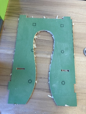
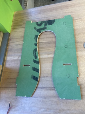
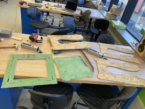
Soon, I was ready to put it all together. We ran into a few small issues. One is that the OSB isn't’ all the same thickness- this causes some issues since I was cutting different pieces for the same project out of two different sheets so some of the tabs were thinner than expected. Another small issue was that the slots in the top piece are slightly misaligned. They should be attached to form an “L” so that the legs run straight down instead of being at a slight angle. This would ensure that it fits properly with the other tabs on the middle shelf and with the new tabs between the legs at the bottom. However, it all still fit together and I actually like the look of that little angle. I can try out this table and then decide if I need to fix the dimensions for next time. I made the tabs that go through the top twice the thickness of the board so that they jut out from the top and provide guideposts for a removable acrylic or glass sheet to be inset eventually.
I am thrilled with what I created this week and can’t wait to use it at home and improve on it for my final project!


I thought this week’s assignment would be a piece of cake since I had successfully made my PCB run the echo program during Week 5 (spoiler: I was wrong!) As recommended, I worked off of existing code for LED blinking and button pressing and modified it for my setup.
My first step was to do an initial test of the board with the LED Blink program that is a native Arduino example. However, it didn’t work! I was still using this Arduino/SAMD pinout conversion to try to figure out which pins on the SAMD corresponded with the Arduino pins I needed to use in the code. However, after a conversation with Anthony, I found out that this conversion is actually garbage! PA14 for the LED doesn’t correspond to 5 as the diagram would have me believe- it actually just corresponds to 14. Similarly, PA08 for the button is just 8 instead of 3. However, after fixing that, it still didn’t work. I suspected a hardware issue and decided to start testing my button instead.

However, soon I discovered that my board was no longer showing up in Arduino! The correct port was no longer visible under Tools>Port. Upon Anthony’s recommendation, I tried typing lsusb into terminal but it gave me an error. After some wiggling around and turning the board upside down, we finally got it to connect. We suspect that it wasn’t showing up because the connection to the USB was weaker, but I’m surprised by that since I shimmed the back with about 5 layers of vinyl!
For my button test, I modified existing button press code to print high/low to the serial monitor based on what the button was reading since I couldn’t use the LED as a way of determining what the button was reading. However, it kept printing “low” indicating the button was never pressed, even when I was physically pressing it. It was time to get some more help from Anthony! He reminded me to turn on the SAMD11C’s internal pullup resistor by changing INPUT in the code to INPUT_PULLUP. However, it still didn’t work.
Anthony helped test with the multimeter and we found several different issues: first, my LED was flipped! I was bummed about that because I had checked for that initially and followed what I thought was the right convention...but it sounds like different sets have different conventions and some are printed underneath in a spot that’s hard to see.
Next, we figured out that my button was soldered wrong! It’s funny because Anthony had even told me originally that there were two orientations for the button and that one would obviously be wrong and one would obviously be right. I thought I had figured out which was which but turns out I was looking at the spots where the face plate curled under instead of where the actual leads were. So I needed to desolder the button and rotate it 90 degrees.
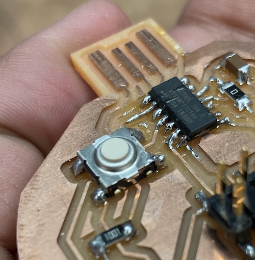
Finally, after desoldering and resoldering the LED and button, I was ready to re-test! The blink code worked and I had a working LED!
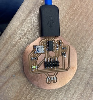
I then used the button to turn the LED on and off and that worked too! However, it was defaulting to have the LED on and pressing the button would turn it off. I switched that around in the code so that the LED would turn on when the button was pressed instead, and voila! It worked!
Now, I am chugging through the datasheet for the SAMD11C. The datasheet covers the D11D and the D11C, so it is especially long, and I didn’t understand most of it. I did find the pinout to be particularly helpful!
Another thing I ended up spending a HUGE amount of time on this week was trying to figure out how to add video to my site. Turns out, there are different ways of converting video to mp4 and not all of them are supported through HTML. I was getting a blank screen when putting my videos up but finally had success when using this website to convert .mov to .mp4. I also edited the template CSS for the first time to get my video and photo to be aligned in two columns within a row!
The group assignment for this week was to compare the performance and development workflows for other architectures. However, most of our lab section used the SAMD11C and everyone used Arduino to program their boards.

This was another week I was super looking forward to! I have done a decent amount of molding and casting before and am a Smooth-On fangirl, so I wanted to pick something that would be a challenge. I decided to try and make a personalized crochet hook since I knew making something long and thin was going to be quite tricky to pull off.
I started out by modeling a crochet hook and adding my name where the size label would usually go.
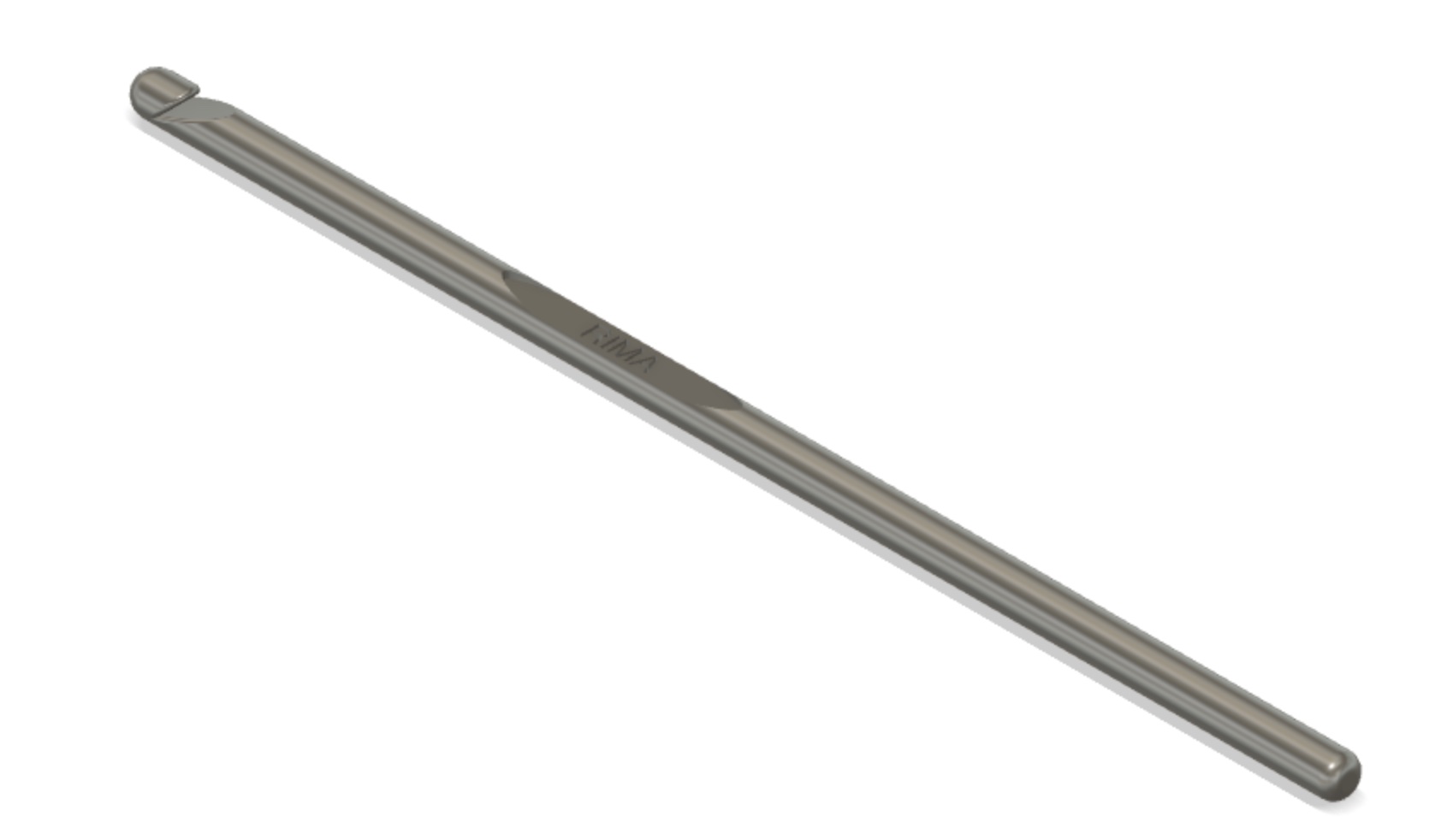
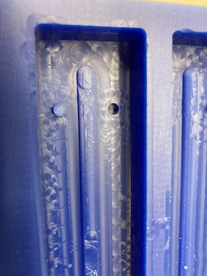
Next, I started to work on a mold. I found this tutorial super helpful, but after doing the whole thing I realized the tutorial was for making a 3D printed mold! This means that my mold was backwards (the hollow space was the size of the crochet hook rather than the size of the Oomoo mold). I might try and 3D print this another time though to try and compare results between molds!
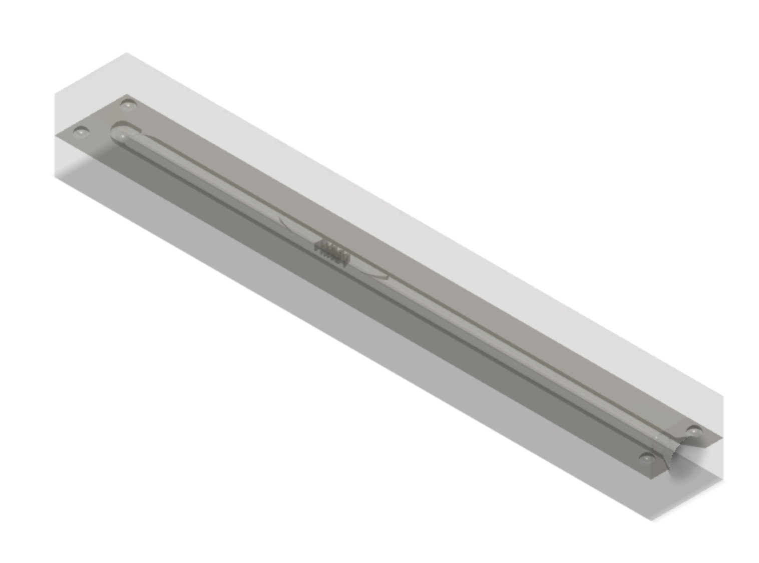
Finally, I created the actual wax mold to be machined. I added registration features so that the mold would be self-aligning. I was planning to add a pour hole to the mold but Anthony said it’s typically easier to just cut that out by hand afterwards. I also realized that the actual hook part of the crochet hook was an undercut, so I would have to post-process either my mold or my parts to get the hook to be as deep as I wanted it. I could have split my mold in the other direction to avoid this issue, but I wanted to try out engraving my name on the midplate of the hook so I didn’t do that. Maybe next time I should try a 4 part mold!
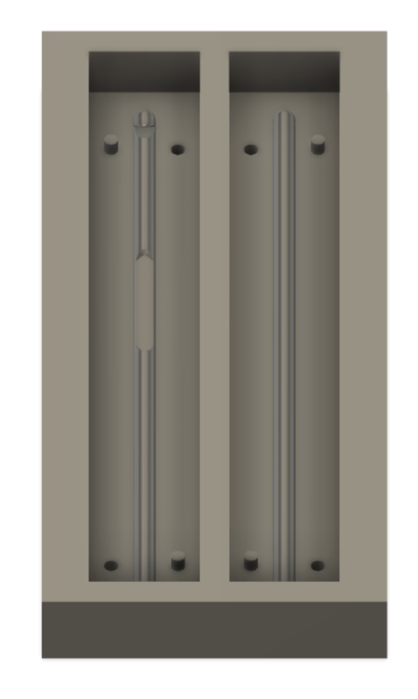
Creating the CNC toolpaths was quite the adventure. I started with a 3D adaptive toolpath with a 0.25” bit. I followed that with a scallop and steep and shallow operation with the same bit. Then, I switched to a 0.125” bit for a final surface finish pass (steep and shallow) and a drill operation to make the registration features. Finally, I had a projection operation for engraving my name with an engraving bit. Anthony helped me finalize the toolpaths and make some edits to cut down the time. One strange thing was that the avoid surface option was giving an error and selecting my whole model instead of a single surface. This was annoying because we were trying to stop it from doing all kinds of unnecessary operations on the edges. After making the required changes to the toolpaths, I was ready to machine!
I started by hot gluing my wax block to the OSB platform. Then, I changed the tool and zeroed it using the touch plate. Machining with the 0.25” bit went very smoothly and quickly. Here is what the surface looked like after all the passes with that tool.
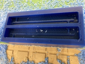
Next, I switched the tool to the 0.125” bit and zeroed it. I learned that if you flip the touch plate over, you can rest it on top of an object which is convenient if you only want to set the z height! This round of machining was very painful to watch because it was super inefficient despite the changes we had made! It spent such a long time cleaning up all the edges and corners that we didn’t care about at all. If I were to redo this, I would use the “trim” to cut down paths on the outer edges and corners of the molds. Here is what the surface looked like after those passes!
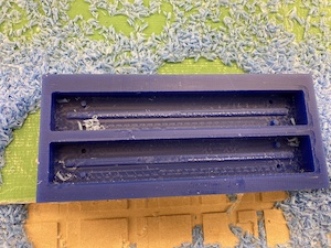
Finally, I was ready to do the projection operation with the engraving bit to try and engrave my name. This was totally an experiment and I had no expectations that it would create something that would be legible in a final model. We started with engraving to a depth (axial offset in the “Passes” menu) of 0.01”. Naturally, this was super speedy to run and after checking it out we decided to go a little deeper. We changed it to 0.03” and liked the way that looked. The letters looked like they might already be starting to bleed together, so it was prudent to stop there.
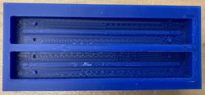
I measured the volume of the mold with water and used that measurement to mix the right amount of Oomoo and cast it. The mold came out great, and picked up my name beautifully! However, there was one small issue...my registration features were backwards! I had holes that lined up and plugs that lined up instead of plugs that lined up with holes. Additionally, the plugs didn’t fill all the way so they were more like nubs. Next time, I would make those holes thicker or do domes instead of cylinders, which is what I had in my initial model. To address the registration issue, I cut off all the plugs and inserted two small screws into two of the holes so that the shaft of the screw would act like a plug and fit into the hole on the other side. This worked wonderfully for registration!
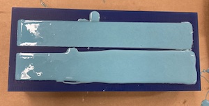
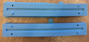
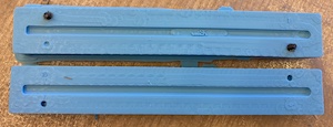
I cut a hole in the bottom of my mold since that part is less of a key feature. I decided to try my mold with epoxy since I wanted something that would be thin enough to pour and turn out strong enough to handle. I rubber banded the molds together and mixed up epoxy to cast with. Unfortunately, during the curing process, the majority of the epoxy leaked out of the mold. I needed to secure it better at more points in order to avoid that. I ended up with a little half hook instead of the full thing!
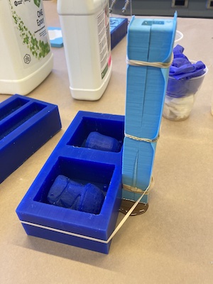
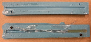
I wanted to see if casting the hook horizontally would be better so that the mold would also naturally clamp together due to gravity. So, I decided to recast the mold and cut a new hole such that I could pour into it from one of the lateral sides. I also decided to do a bit of post processing on mold to make the hook part more hook-like. I used a soldering iron to melt into it a bit and used tweezers to scrape it a bit as well to deepen the hook feature. I also thought I’d try insert molding the screws into the mold so that I wouldn't have to push them into the holes after casting it.
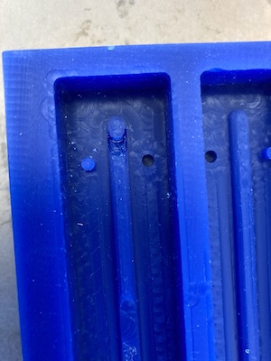

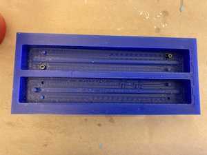
The new mold came out great, except for the fact that insert molding the screws was unnecessary- the spots I put the screws in were the ones that were becoming plugs in the original design anyway. Clearly my spatial recognition skills need work! Insert molding worked well with the Oomoo, but because of my error I had to pull out the screws and put them into the other holes by hand instead!
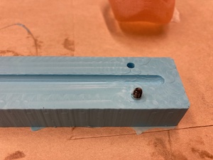
I tried out both molds with Hydrostone to get a sense of how the molds were functioning. The horizontal mold cast seems to be a little better but I also opened the vertical one a little too early. I’m really impressed with how well it captured the feature with my name on it! The actual hook isn’t usable yet since it’s still not deep enough. Hydrostone is also not the most ideal material since it is brittle in that shape. I also figured out a better way to clamp the vertical mold so that the casting material doesn’t all spill out- I am using popsicle sticks to reinforce the sides and rubberbanding in both directions.
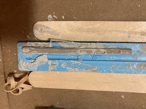
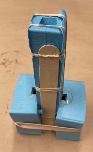
I am now trying to cast both with resin that I have at home to see if I can get better results now that I have a better understanding of how these two molds work! I tried laying the vertical mold diagonally to get the resin to flow all the way through. However, the vertical mold still only filled halfway and the rest of the resin flowed out.
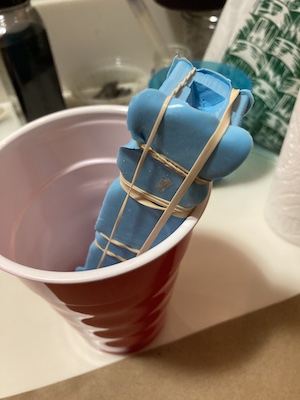

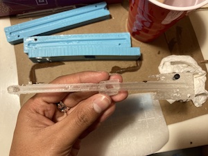
As I predicted, the horizontal mold worked much better with the mold filling completely. There was quite a bit of flash, but I scraped it off with an exacto knife. I also had to cut off the extra from where I poured the resin into the mold. Finally, I cut the hook deeper using the knife, but it snapped off midway. Once the resin has fully cured, I will superglue it back together.

For this week’s group assignment, we have been making a chart of the different materials available to us and their casting properties.


We are now in the portion of the semester that I am intimidated by! I am super excited to be learning more about electronics but it is also something I find pretty overwhelming, so I’m trying to be creative about using these weeks towards my final project and trying to frontload my work.
First, I decided I want to make one board for a few of the upcoming weeks- in particular, input/output and networking/comms. As such, I am using an ESP-32, which can interface with wifi. I am also using this towards my final project, so my output will be a speaker. For my input, I’d like to make my own variable capacitor like this one, so I’ll be using copper sheets for step response.
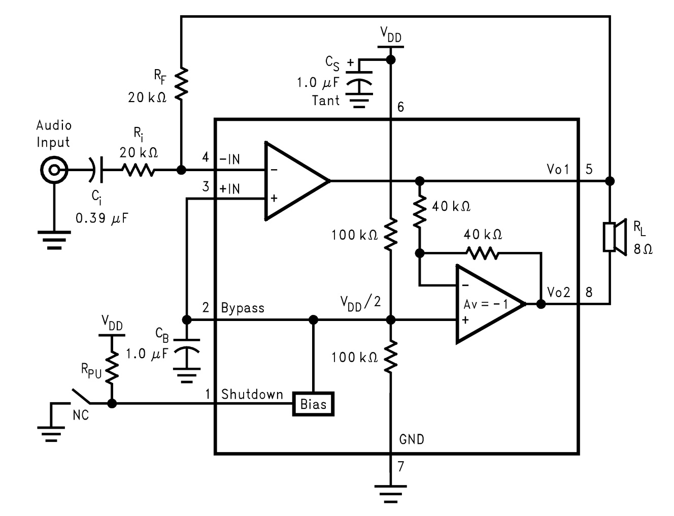
This meant I needed to make a Frankenstein board made up of several examples smushed together! I began with this example for ESP. This awesome resource from random nerd helped me understand which pins on the ESP are ok to use for input/output. I then added in elements from the load cell step response board for my input. Finally, I found out that the audio amplifier we have access to in the inventory is the LM4871, so I looked at the datasheet for that part to find a “Typical Application” and recreated that in my board as well.
Since all of these are assuming different microcontrollers, I had to do some conversion of ATtiny45 to ESP-32, and this pinout this pinout was very helpful for that.
I definitely had an easier time in Eagle this time, although I was sad when I realized that the trace width for routing is auto-set to 6 mil, which is too small for us. We need at least 10 mil, so I had to go back and redo all of it. I also got great advice from Anthony about naming all of my nets. Finally, I learned how to edit a part footprint in Fusion as well since the space between the pins of the ESP was way too small. I have a newfound love of 0 ohm resistors that save the day anytime I’m in a sticky situation! I’ve really come to enjoy the process of figuring out the best way to route the PCB- it’s really like a puzzle and it’s honestly pretty fun. My intuition for the actual electronics is improving but not quite there yet!
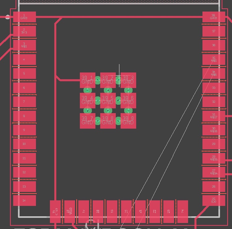
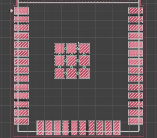
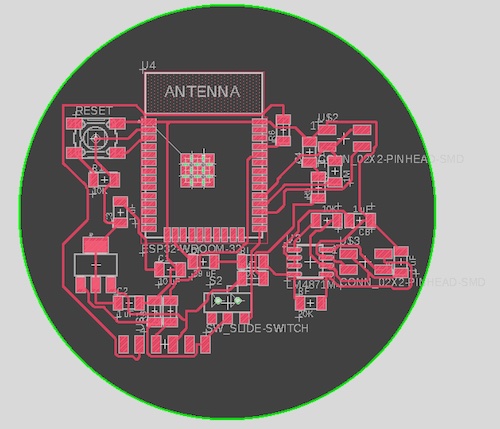
I decided to mill my board on the Othermill this time since I have been primarily using the Roland. I learned how to export a Gerber file from Fusion (go to the Manufacturing tab!) and set up my file on the othermill. It exported a bunch of different files, but turns out that the one called copper_top had the traces and the outline in it. I was able to toggle those from the Bantam Tools software to do the traces with the 1/64 endmill and then the outline after with the 1/32 endmill. There was a bit of a snafu with getting started since the board thickness was auto-set to 1.80mm instead of the 1.55 mm that it actually is, so the traces weren’t milling through all the way. However, we fixed that easily and were able to restart the job! For some reason, the side of my circle got cutoff, but that’s not actually a functional element so I’m not too mad!

I was able to solder everything onto my PCB with very few issues. I did have to swap out a couple of components with parts that we have available, but double checked with Anthony that it should be ok. I had to switch a 0.39uF capacitor for a 1uF capacitor (though I did get to see Anthony’s books and books of capacitors with very specific values, which was cool!) I also swapped out two 20K resistors for 10K resistors. In this case, the values of those resistors only mattered relative to each other, so it shouldn’t influence the performance of my board. For the ESP, I started by trying to solder each pin individually, but they started glomming together, so I instead used the method of putting a ton of solder on the connections and then sucking away the extra with solder braid. This worked relatively well to give clean connections. However, some of them looked like they might still be connected to each other when they shouldn’t be.
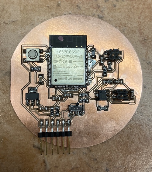
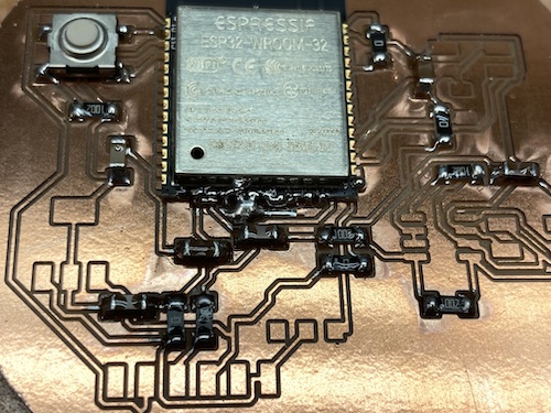
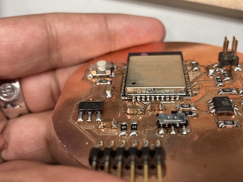
Once everything was soldered, I used a multimeter to check for shorts. I found a few and Anthony helped me get them taken care of by adding more solder and then wicking away again. This removed all the solder from the faulty bits and I resoldered them individually- this time with a smaller iron and thinner wire that allowed me to easily solder individual pins.
Finally, I soldered some wires to pieces of copper tape that I would use as my actual source of input. After a few mishaps and misplacements, I connected one to the pin connected to IO5 in my circuit.
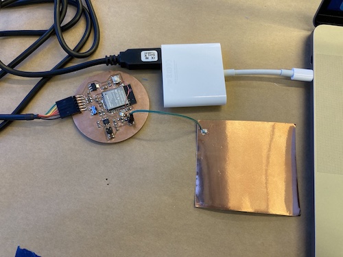
Then began the fun of trying to program the board! Turns out this board doesn’t need a bootloader- it just has to be plugged into the USB. Anthony had a wire that goes from the 6 pin connector to USB but in theory my programmer from an earlier week will also work. Arduino recognized the board and I downloaded the ESP IDE using these instructions For me, using the board “ESP32 Dev Module” worked since the WROOM isn’t listed as one of the options.
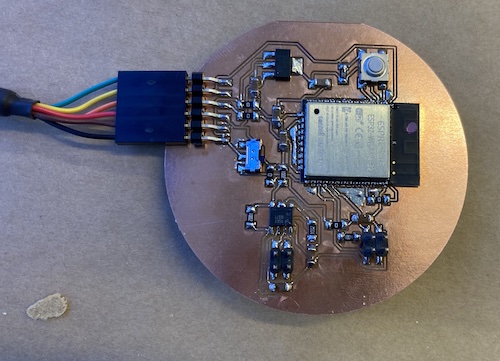
To communicate with the ESP, it is helpful to have the serial monitor open with 115200 as the baud rate. In order to upload code to the ESP, the switch on the board needs to be pushed to the right and then the button needs to be pressed. This will send a message saying that the board is ready to download code. Then, once code is uploaded to the board, push the switch on the board to the left and press the button again to run the program.
I found some great sample code from this site from a previous year. One pin is being modulated from high to low voltage and the other pin is reading out the response. The difference between the response at high and low voltage is printed out. While doing this, I found that which pin #s correspond to the Arduino pin #s is rather unclear. After some experimentation with the multimeter, we found that the GPIO numbers in this pinout are the numbers to use.
During the process, however, we discovered another issue. The pin I wanted to read was pin 5, which does not support analog read. The ADC section of this guide lists the pins that do support analog read. As a result, I had to sever the connection between pin 5 and the rest of the circuit and use magnet wire to reroute that to pin 39. Once I did that, I was finally able to see the difference between the values being printed when I touched the copper pad. Yay!
Eventually, my goal is to get something similar to the rotation example here so that I can create my own dial switch. There are a few more steps to get there involving adding additional elements to my circuit and figuring out the appropriate thresholds within my code, so I am stopping here for now and will hopefully do more on this during the upcoming week!

This was such a frustrating week for me! I wasn’t able to get things set up at home because I don’t have the 6 pin to USB cable, so I got a late start for troubleshooting. Since I live in a dorm with a makerspace, I was able to do a bit of soldering before coming in. The magnet wire I used to reroute my pin last week broke, so I fixed that. I also soldered two wires with female ends to the two sides of the speaker so that I could easily connect them to the header.
I had so many issues with this board on the route to getting the speaker to play sound! I started with sample code I had seen several people from years prior use successfully (linked here). My first issue was that I didn’t have the speaker circuit connected to an external power source. So I hooked it up to one of the power supplies in EDS and set it to 5V since 6V is the absolute maximum for the amplifier. However, it was still not working.

My input was connected to pin 13, but when I probed it with the oscilloscope, I was not seeing anything besides a bit of noise. After probing with the multimeter, I discovered that this pin was shorted to ground! Not ideal at all! It was not a visible short, so after a bit of time trying to fix it with solder wick to no avail, I figured the connection was likely underneath the ESP. I decided it would be easier to reroute the connection to a different pin the way I had for inputs week. So, I switched it to IO25 (pin 10).

I also made a pared down, simple version of the code that would just play one tone constantly instead of cycling through notes. I figured this would make it less likely that we would run into issues in the code. The ESP does not use Arduino’s native tone() function and instead uses ledcSetup(), ledcAttachPin(), ledcWriteTone(), and/or ledcWrite(). I had been using ledcWriteTone() but Anthony suggested I switch to ledcWrite() instead. Eventually, I am also interested in looking into DAC output.
Switching to IO25 also wasn’t initially working…and then we discovered that it had also gotten shorted to ground in the process of attaching the jumper wire! That was easily remedied and we were back in business. Finally, probing with the oscilloscope at IO25 showed the square wave we expected and the frequency I had input! However, the speaker still wasn’t producing any noise.
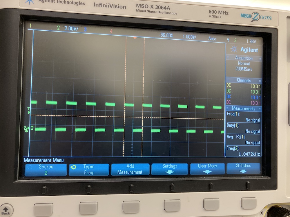
Again, we were back to probing with the multimeter. Some weird things happened involving the directionality of the multimeter… we still haven’t totally figured that out! However, during the process, we realized that the sound would buzz if I connected the shutdown pin of the amplifier to the input. This was very confusing! Warning- the sound in the video is very unpleasant.
Finally, we realized that the amplifier shutdown feature is enabled when the shutdown pin is high. In the typical application, this pin is connected to a pullup resistor connected to a switch. When the switch is pressed the shutdown pin is connected to ground and enables the amplifier. When the switch is open, the pullup resistor disables the amplifier. I had left the switch out of my design thinking that it was unnecessary, so mine was always connected to the pullup resistor and as a result always had the amplifier disabled! So, I desoldered the resistor and connected the pin to ground instead. Finally, the speaker works! Warning- the sound in the first video is very unpleasant. The second video plays a little song (code for that is in the second download below)!

Finally, this week is the one where I thank myself from a few weeks ago for putting in the initial effort to combine several board designs! This week, things went really smoothly and I was able to test a variety of wifi and Bluetooth features on the ESP32-WROOM.
I found this student’s exploration from a previous year to be a really helpful framework to follow to get experience with different features on the ESP32.
Randomnerd also has this great documentation for Wifi Library Functions using the Arduino IDE and information about how to appropriately reference the SSIDs and Passwords that come up when trying access the ESP32.
Finally, the examples in the library along with Neil’s example code were very helpful and will be linked below with the modifications I made.
I started with the WiFi scan example to make sure that the ESP32 was able to recognize nearby WiFi networks before I tried to connect to one. As part of the scan, it also prints out a number indicating the relative strength of the signal.
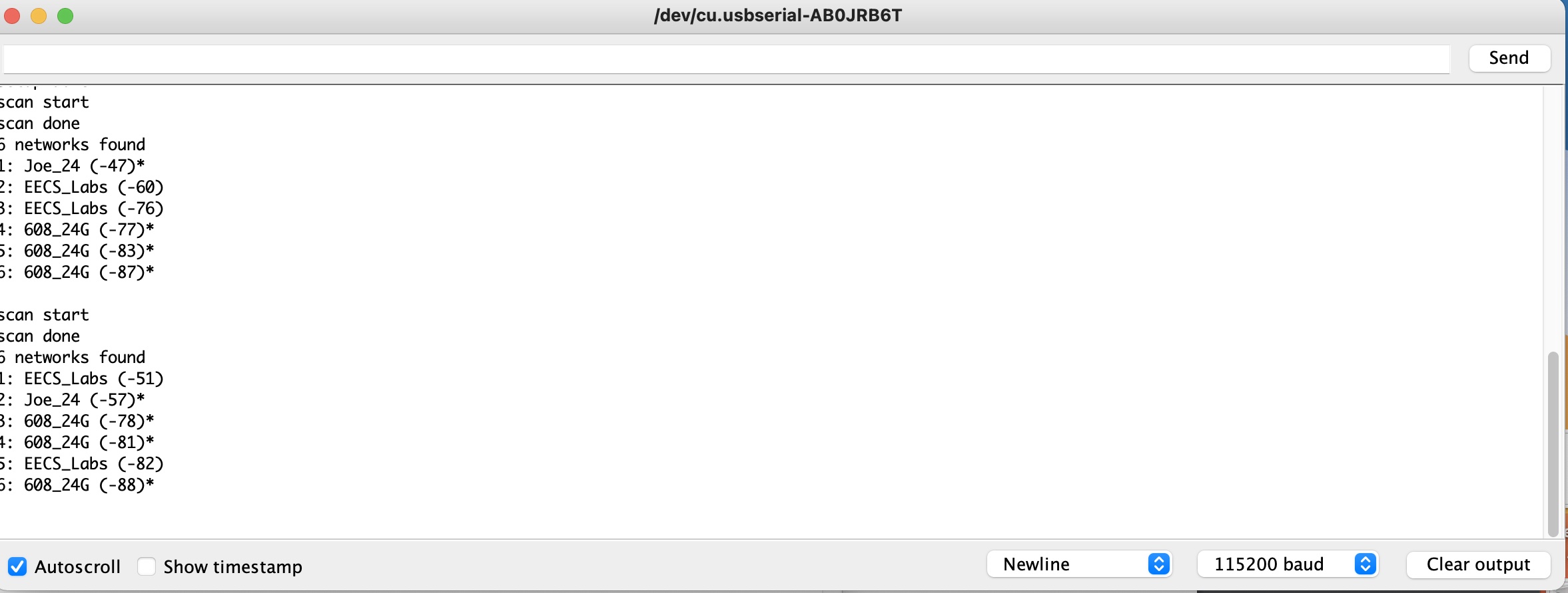
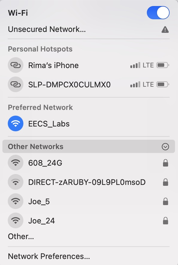
Next, I wanted to see if I could control the speaker on my circuit through WiFi. The WiFi Access Point example does something similar with an LED, so I was able to modify it slightly to work for my speaker and it worked beautifully! In order to do this, you need to connect the device to the WiFi network “yourAP” and use “yourPassword” as the password (or change these values). Then, go here in a web browser to turn the speaker on or here to turn it off. This worked perfectly both on my computer and phone- super cool! I might end up using this functionality for my final project.
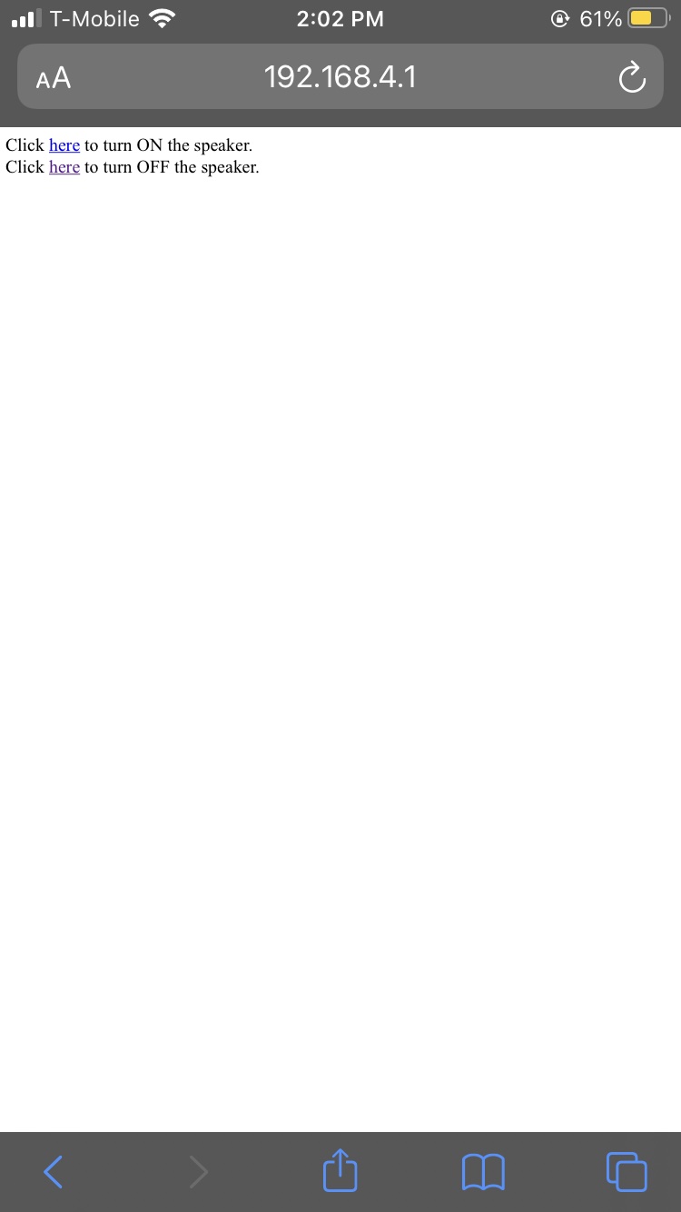
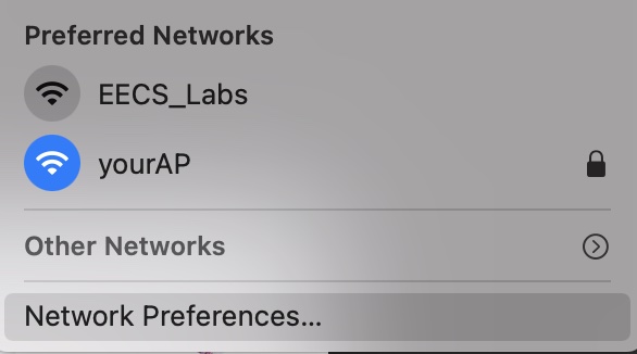
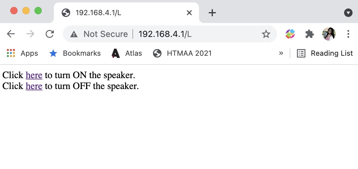
The last thing I tried was reading off content from a website online. I created a hello world page on my class site here and modified Neil’s code to point to my site. The ESP32 was successfully able to read back what it saw on my site! For this test, I learned that to join a WiFi network that has no password, WiFi.begin(ssid,password) should just be modified to WiFi.begin(ssid).
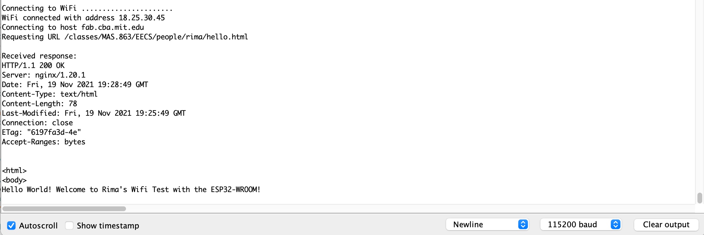
I only had partial success with Bluetooth- my computer was able to recognize the device but not pair with it. The student whose work I was following from a previous year had the same issue, so I am wondering if there is a step we are missing. 12/1 Update: it might be because the board is covering up the antenna and the copper is dampping the signal as a result.


This week we were tasked with writing an application that interfaces a user with an input or output device we made. I decided to use Processing, since the format of the software is similar to Arduino. I started with some of Processing’s basic tutorials to get familiar with how it operates.
I saw this student from a previous year who used ControlP5 to make a GUI. This example showed how to make buttons, toggles, and other switches using ControlP5 I experimented with it a bit but found it to be a lot less flexible than just coding directly using Processing.
I also followed this tutorial to learn how to connect Arduino and Processing. It took me some time to figure out the right port that corresponded with my device, but I was able to do so by checking the order of the list on Arduino. I used this to turn an LED on and off by clicking on the Processing drawing.
Next, I wanted to use Processing to create an interface to select frequencies to play on my speaker. I worked off of this example to learn how to make multiple buttons in Processing directly and added text to them to label the frequencies they will play on the speaker. I also wrote code in Arduino to read in the input from Processing and play the corresponding frequencies on the speaker.
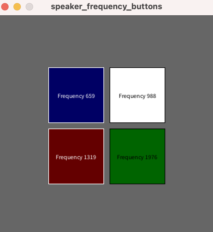
This is a “software only week” but I will need to go into lab on Monday in order to test my device and see if it works. For now, I can see that the output from Processing is correct- the screen changes color corresponding to which button I press and the correct number is printed. Simultaneously, I have verified that the Processing to Arduino connection works using the LED test as well, so I feel fairly confident that it will work!
Updates after testing: I learned that it was not so simple! First, I learned that you cannot have the serial monitor open if you are trying to control something using Processing. That was quickly remedied by closing the serial monitor window. When I tried testing my speaker code, the speaker only played one note and wouldn’t change when I clicked on the different squares. After a bit of debugging, I realized that no matter what frequency I gave it, the speaker was playing the same tone. I made some changes based on the old melody code that I had- changed the channel to 0 instead of 1 and used ledcWriteTone instead of ledcWrite (makes a lot of sense now that I write this out…)! Finally, it worked as intended- see video below!