Week 01: laser cutting and vinyl cutting
Week 02: electronics production
Week 03: 3D scanning and printing
Week 04: electronics design
Week 05: computer-controlled machining
Week 06: embedded programming
Week 07: molding and casting
Week 08: input devices
Week 09: output devices
Week 10: interface and application programming
Week 11: networking and communications
Week 12: mechanical machine design

Final project


For my final project, I intend to construct and automate one of Albrecht Duerer's lesser known drawing machines ca. 1525. Though Duerer is most famously known as a Renaissance artist, he was also an early contributer to visual perspective and mathematical scholarship through his drawing instruments. His interests in human proportions and movement led to two significant drawing machines in his late career, the Snail (die Schneck), the Spider (die Spinne), and the Snake (die Schlange). It wasn't until recently, while whatching a lecture by Bernard Cache titled, "Duerer - Vitruvius - Plato. Instruments of Thought" that I became aware of the lesser known instrument, the Snake. While only a diagram of this instrument exists, we can clearly see "dials" and "rods", which free the instrument from planar movements, giving it the range to simulate movement in 3D space, which he calls the serpentine line. And although many hypothesis suggest why this instument was drafted its purpose is still unknown.

In his more famous perspectival devices, the eye of the observer plays a fundamental role, however, the Spider and the Snake were constructed to generate points and lines. The Spider (Fig. 01) produced 2-dimensional lines (Fig. 02) and the second, the Snake (Fig. 03) is thought to be used to draw a variety of lines that Duerer would call a serpentine line.
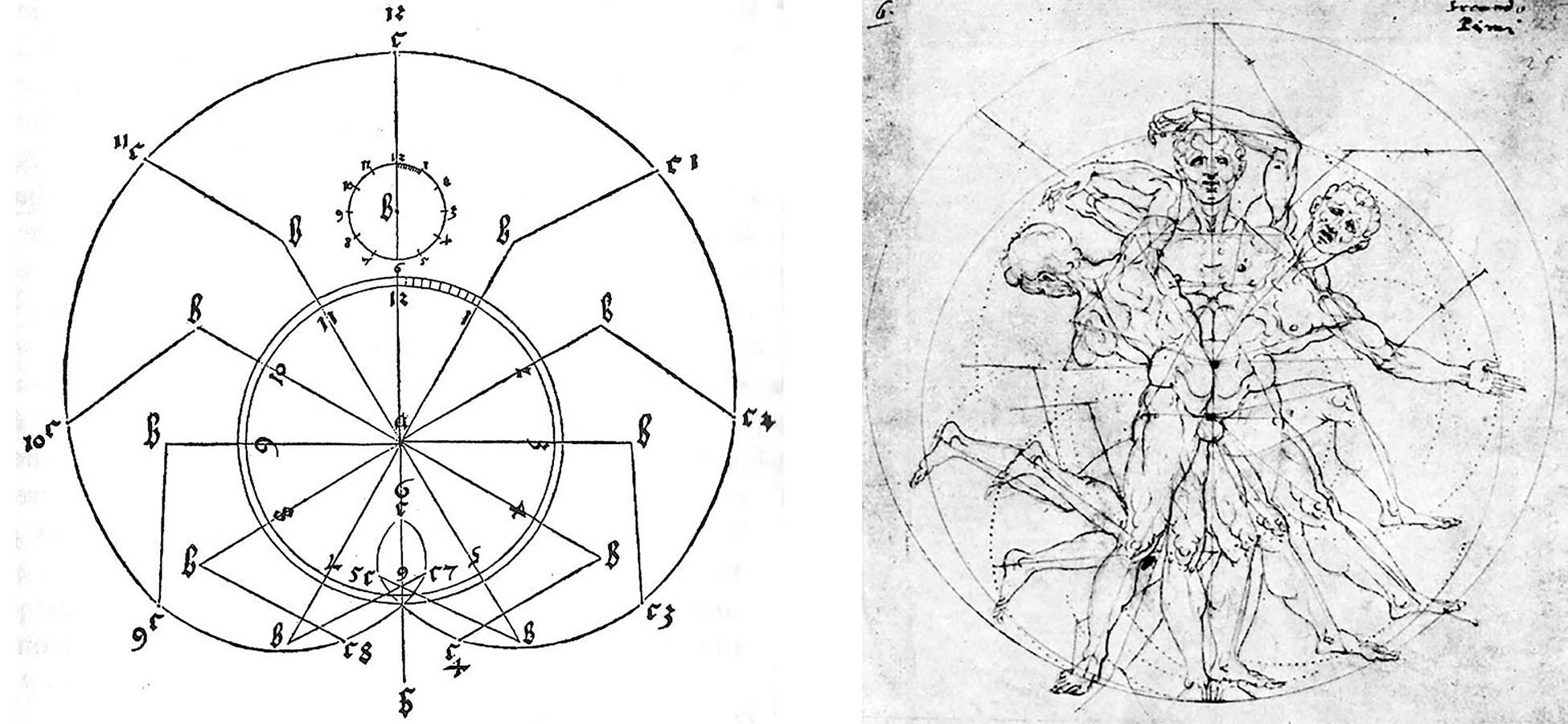

Fig. 01 and Fig. 02
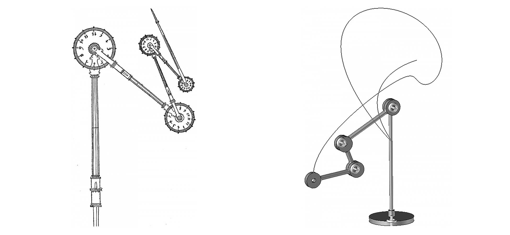

Fig. 03 and Fig. 04


Pictured above is the only record of the Snake instrument (Fig. 03) and a computer model (Fig. 04) Bernard Cache generated in ca. 2012. In these two illustrations you can see the "dials" and "rods" Duerer references in Underweysung der Messung, the book where the original diagram is published. In this text, Duerer describes how to construct die Schlange, an instrument that can be used to draw a variety of lines, the serpentine line (paraphrased by Bernard Cache):

1.) The instrument should be made with few or many dials and rods, according to the intended applications.

2.) The rods shall be arranged in a manner that they can be advanced by degrees and can be shortened or extended.

3.) The rods can be pulled apart or pushed together, also by degree, so that they become shorter or longer.


A formal analysis of these instruments was initially presented by Bernard Cache in 2012 at Cornell University in a lecture titled, Instruments of Thought. Since then, Cache continues to write, lecture, and produce related material on the subject.
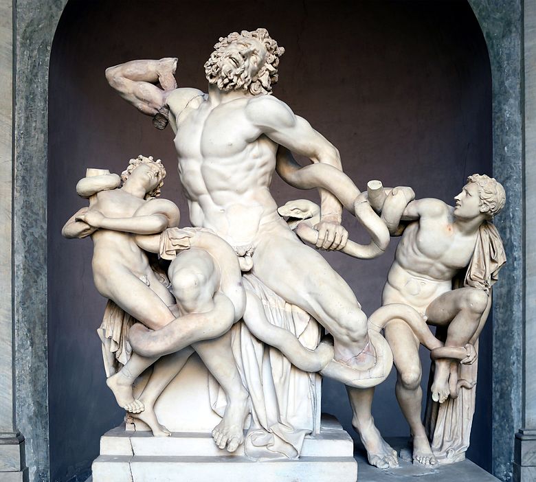
Fig. 05

While the intent of this instrument is still unclear, many have hypothesized that it was used in the fabrication or restoration of sculpture, one example is Lacoon and His Sons, (Fig. 05). Regardless of intent, this tool has the potential to construct non-standard objects with repeatable variation. A drawing instrument that never constructs the same spline twice.

Through the calibration of the dials and rods, the data points relative to the central leader are endless and varied. Unlike many of his other instruments where he includes lengthy notes, and formulas on the instrument’s performance and anticipated results, Duerer, did not show us anything more than a diagram of the Snake instrument. At the time this instrument would have been used to construct what was called 'superior geometry' which simply refers to a line that could not be constructed with a ruler and compass. In other words, a spline putting emphasis on the parametric design and mechanical variations in the 15th century.


Simulation and testing:
To simulate the path of the drawing instrument, I am using Unreal Engine. Fig. 06. A video game engine, which I can use to rig the device to control the direction and speed of each dial and rod.

Fig. 06


Here we can see the path of the serpentine line, as the end is recorded with disappearing orange line. Simultaneously, the end is also recording several xyz coordinates per second (blue numbers streaming alongside the left edge of the video) which can then be extracted and recorded seperately. In Fig. 07 and 08 you can see the resulting spline, which can be used to generate new forms.

Fig. 07 and Fig. 08


Fig. 09


Parametric design and fabrication is not an architectural principal, but an ancient inquiry borrowed from other forms of art and production. I am interested in the tools, mechanisms, and protocols, that drive the discipline rather than the production of buildings.


In the weeks to come, I will be using the inputs and outputs of the instrument to construct a series of relational things: 1.) object, 2.) video, and 3.) machine to open the conversation beyond the role of performance toward the literal, perceptive, and simulacrum ideas of technology.


Construction:
To aid in the construction of this instrument I purchased 3 aluminium tripods ($14/tripod) to use the light-weight adjustable legs. This was extremely helpful, because weight and torque quickly became the most challenging obstacle in this project. The legs of the tripod were deconstructed and reconstructed to varied lengths. Then connected together with 3D printed joints and integrated stepper motors. In addition to the tripods, I also purchased stepper motors. Following the lessons learned in week 09, I knew I needed a light weight stepper motor with decent torque strength. This was difficult to find, the stepper motors with optimal specifications, were too expensive. So I took a risk with a cheaper motor from Amazon, which worked okay. More on this further down the page.

After disassembling the tripods into their component parts, I began to draft connections for the joints. It took a few attempts to get the tollerance correct for a friction fit that could be secured with bolts. The result was fairly successful, and I was able to properly link the rods at each joint.


With a plan for the assembly, I started to shifted focus toward the stepper motor and microcontroller. I began to work on the Sam D11D from week 09, but ran into issues with bootloading and communication. So after talking with classmates (Thanks Kim and Demirican) they suggested using an ATTiny 1614F breakout board and a 6-pin header to an FTDI cable. This simplified the process, and it became much easier to identify errors.

The stepper motors used for the final project connect to a ULN2003 driver board, which I connected to my ATTiny microcontroller via 4-pins and power.


To deliver power, I used an adaptor to reduce the voltage down to 12v for the stpper motor and milled a small breakout board to reduce 12v down to 5v, preventing the microcontroller from burning out. Then to connect pins to power, I found these plastic sleeves that shrink around bridged wire with heat. then the PCB's are connected to the rods with 3D printed parts that are daisy chained together to provide power to the upper branches.

The final assembly is chaotic, but it works.


Here you can see the stepper motor rotating on its own, and with the rod. Yay!


The next obstacle was extending the stepper motor shaft. In this design, each branch controls the rotation of the next. After attempting to epoxy and even solder a threaded rod to the stepper motor shaft (I was desperate), I discovered a small brass collar from a plumbing supply store. This narrow collar had enough tollerance to create rigid connection between the stepper motor shaft and the threaded rod with JB Weld (epoxy putty).


Now with the individual parts working, it was time to fully assemble the Snake. At first the components all worked, but when running the three motors simultaneously, former issues returned. Regardless of how I draft the code: clockwise/counter-clockwise, fast/slow, stepped/continous the same issue persists. The first (base) motor and the third motor work perfectly, but the second motor does not have enough strength to rotate the rod, now that it has been loaded with additional cantilevered weight. My next attempt will be to add a couter-weight to the second motor, reducing the amount of torque. Over IAP, I will continue to work in this machine, as I am very excited to see it fully operational.


With the recent failure, I shifted focus toward creating a video that demonstrates the historical and theoretical value of Albrecht Duerer's drawing instrument the Snake (die Schlange).