Final Project
— final — 3 min read
Initial Idea
My initial ideas (clearly, will change during the semester) is to create a board where one can draw sine waves and create harmonies. Essentially, allowing anyone with no musical background to experiment with music creation just by drawing waves. The way I imagine this project is by having a glass table, and underneath it LED lights. With some pressure sensors, we can determine the location in which the user touches the glass, and have corresponding LEDs turn on.
I found this idea compelling for a few reasons:
- It relates to my research field - Telecreativity
- It combines many different form of data manipulation - draw, music, and signal analysis
- It is large size and easy to demonstrate
Then the wave can be calculate based on the turned on LEDs and produce some harmony using a simple sound processing algorithm.
Modified Idea
Following a conversation with Neil, I realized that my project is actually two different projects - One is detecting hand gestures on the board and translating into LED manipulation, and the other is the transformation of LED matrix to music and playing the music within my device. So as much as I like music, I think a more "How-to-make" idea would involve sensors and the fabrication of a big device, so I have to adjust to it.
Enters a new idea: ATARI Pong Electronic Table
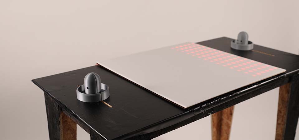
I'll explain; Since I already started thinking about LEDs as identifiers on a glass table and I kind of like it, I would rather use them not to play music tones, but as the grid of the actual game. This idea already is inspired by ATARI's actual table which was release in 2019 and sells for $4347 at the moment.

So the way this will be implemented in my prototype is different than ATARI's idea. First, the controller will not be a spinning knob, but rather an actual handle (like air hockey). second, I can represent my entire game with a LED strip. I made some planning and I think I understand all the missing components I have now. Will try to use the week assignments to gradually come closer to what I need.

As far as I understand, here is what I need to work out:
- 3D print the air hockey handles
- Design a strip on the table for the handle movement
- Two infra red sensors to locate the two handles
- LED strips to represent the game
- Program the game in some machine-readable format
- Create the actual big table
System Design
As a first step I would like to lay out all my components:

The game will be programmed on a SAMD21 board and displayed over (potentially concatenated) LED matrix. Since the sensors are relatively far from each other, it makes sense to create some sort of a networking model where one master board controls the display and two secondary boards transmit data to the master board. This network can be completely wireless given that computation from distance data would be performed on the secondaries.
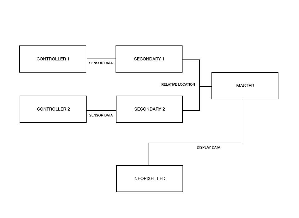
What does it do?
It is a multiplayer game that demonstrates physical and virtual interaction.
Who's done what beforehand?
I haven't found any reference in HTMAA for a pong table or pong game altogether. However, as I stated above, a commercial version of the PONG table exists already. In 2017 Rony Schleien made 2Square2 which is an LED-powered board game which has a lot in common with my project.
What did you design?
I designed the table itself (CAM/CAD), the controllers (3D print) and the sensor interaction. The game design already existed in the 70s but I re-program it to match my hardware. In addition, I designed a LED screen made of 20 LED strips concatenated.
Controller Design
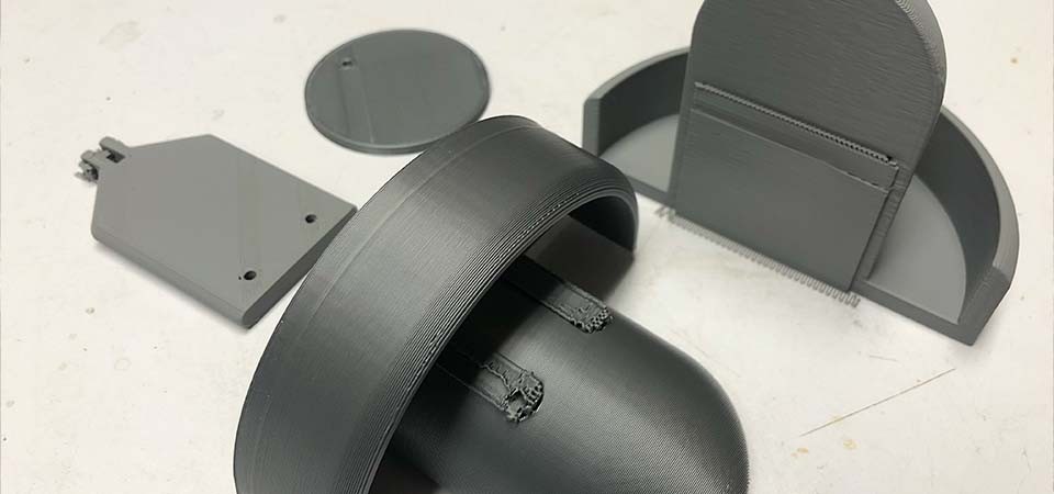
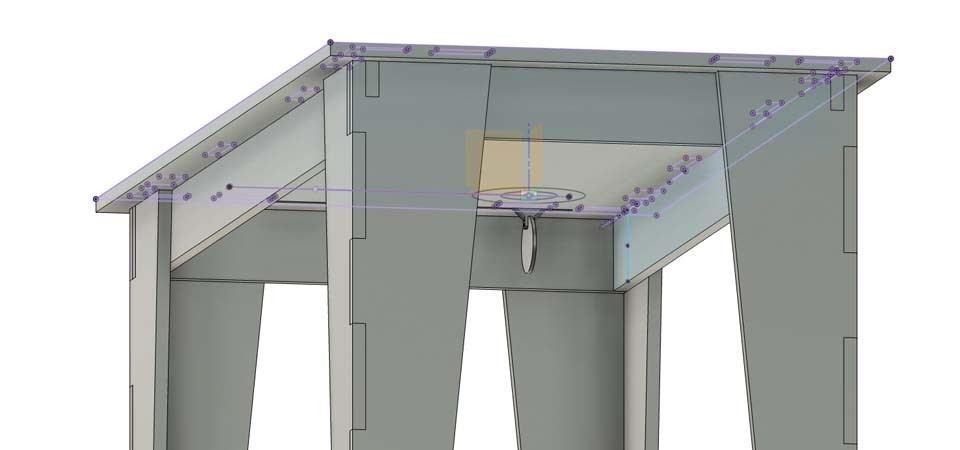
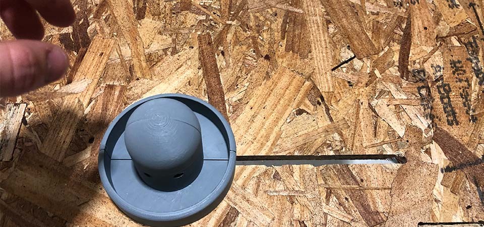
In order to fit in the slide I had to make some tweaks to my controller 3D printed component. The idea is to have the controller on top of the table but have some mechanism below the table that serves as a target to the TOF sensor. I decided to divide into sub-components and assemble them with screws.

So now it fits on my OSB table:
LED Screen
The entire game will be displayed on a LED screen. Ideally, I wanted to use LED strips instead of a ready-made matrix so that I can control the size of it to precisely fit my table design. I found this WS2812B LED strip which looked spaced enough to fit 14 LEDs on each row of my matrix. So I snipped the strip into 20 pieces and made small wires to solder them all together.
I also had to cut this very precise cardboard to hold together all my LEDs.
Electronics
In addition to my breakout SAMD21 board that I made for inputs week, I still had to have another board to drive the sensor on the other side of the table.
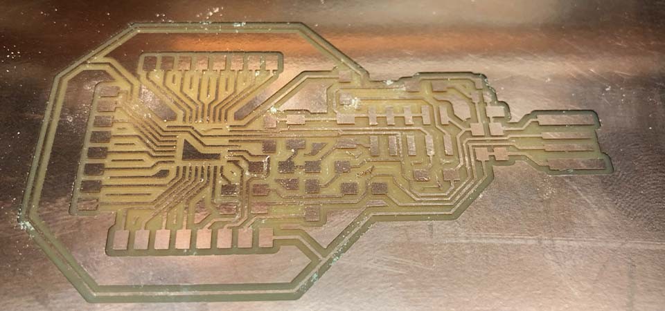
I used an Arduino Mega to communicate between the two boards and to display the LED screen on 5V. Overall this is what my electronics system looks like under the table:

So all together this is what the system is comprised of:
- 2x TOF sensors
- 2x SAMD21 breakout boards
- Arduino Mega
- 280 LEDs
Final Result
