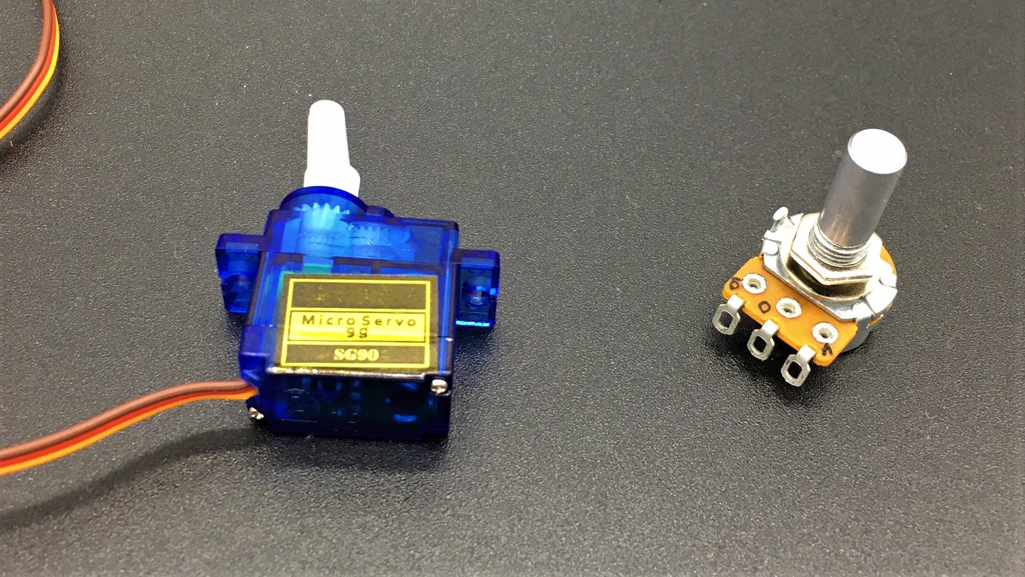
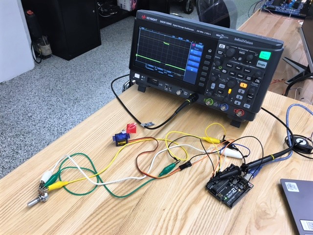
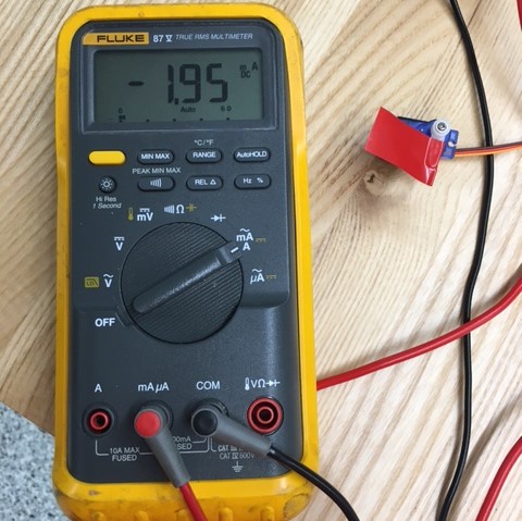
I did not plan to use these devices in tandem on my final project, but for this week’s assignment I decided to use the potentiometer to control servo motor position. Due to my poor board design, I had to solder on jumper wires to power these components. It is on my to-do-list next week to design and fabricate a better board. My tangled mess of a setup is shown to the left. The servo motor required 5 V and the potentiometer required 3.3 V. Based on my limited coding experience, I wasn't surprised when nothing happened after I ran my code. Using an oscilloscope to investigate, I discovered that the potentiometer was providing a varied input to my microcontroller, but this did not correspond with a change in the microcontroller’s output signal to the servo motor.
This video shows the varying potentiometer input to an analog pin of the microcontroller. The input varies from 0 to 3.3 V.
To verify functionality of my wiring and components I swapped my PCB for an Arduino Una board. I arranged my Arduino Una board per
this Arduino Project Hub page. Using the Arduino Servo library, I was able to control servo motor position with the potentiometer.
This video demonstrates the ability to control the servo motor with a potentiometer. The oscilloscope in the video is probing MCU output to the servo motor. This enlightened me to the wave form and duty cycle necessary to move the servo motor.
My board contains a SAM D11D microcontroller, which is not compatible with the Arduino Servo Library. Therefore, I had to develop code to create the necessary wave form to move my SG90 servo motor. My initial wave forms did not move the servo motor, so I revisited its
datasheet to determine duty cycle information for the servo motor.
This plot from the datasheet shows that the pulse-width modulation (PWM) must have a frequency of 50 Hz (period of 20 milliseconds) and the on-duty cycle must range from 1 to 2 milliseconds.
To simplify my setup, I decided to remove the potentiometer for the time being and developed code to cycle the servo motor through its range of motion. My code is hyperlinked to the below image, and the video shows the servo motor cycling 90 degrees, with its PWM wave form captured on the oscilloscope.
The SG90 servo motor has a 180-degree range of motion. I designed my code to shift servo position at 60-degree increments, but as shown in the above video it only shifted from 0 to 90 degrees. I guess I still have few bugs to work out in the code.


